K0582 Revision B
May 2015
23
ii.
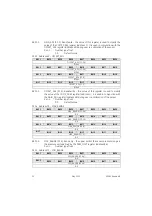
Check the configuration data write access status (optional).
Read STATUS: WENB <0 [3]>
0b1 = configuration data write enabled
The configuration registers may then be modified by writing the new user values to
the appropriate registers. If the new user values are to be permanent, the following
step must be performed:
iii.
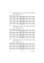
Save the register data to non-volatile memory.
Write 0b1 to STATUS: WRITE <0 [5]>
Finally, the configuration data registers should be re-locked to prevent further
changes from being made:
iv.
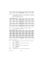
Disable changes to the configuration data registers.
Write 0 to ACCESS: ACCESS <5 [31..0]>
Modifying the I
2
C-bus address
4.4.2
All DPS 5000 sensors are supplied with the I
2
C-bus address set to the default value
of 2. The I
2
C-bus address may be changed by the user by writing the desired new
address to the I2C_ADDR register
9
. Allowable address values are 1 to 127.
For example, to change the I
2
C-bus address to 64:
i.
Unlock the configuration data registers as described in section 4.4.1.
ii.
Update the I
2
C-bus address.
Write 64 to I2C_ADDR: ADDR [7..0] <66 [7..0]>
iii.
Save the new I
2
C-bus address to non-volatile memory and re-lock the
configuration data registers as described in section 4.4.1.
iv.
Reset the sensor. Either power cycle the sensor or:
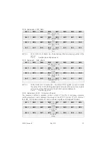
Write 0b10 to STATUS: RESET [1..0] <0 [15..14]>
The sensor will now respond to the new I
2
C-bus address.
Changing the auto-update period
4.4.3
All DPS 5000 sensors are supplied with the auto-update period set to the default
value of 100 ms. The auto-update period may be changed by the user by writing
the desired new period to the DELAY register
10
. The allowable period is between 1
and 1999 ms in 1 ms increments.
For example, to change the auto-update period to 1.512 s:
i.
Exit the automatic update mode (if applicable).
Write 0b0 to STATUS: AUTO <0 [8]>
ii.
Unlock the configuration data registers as described in section 4.4.1.
iii.
Update the auto-update period.
Write 1512 to DELAY: DELAY [15..0] <85 [15..0]>
iv.
Save the new auto-update period to non-volatile memory if required and re-
lock the configuration data registers as described in section 4.4.1.
9
A change of the sensor I
2
C bus address will not come into effect until the I2C_ADDR register has been
modified, copied to non-volatile memory and the sensor is reset via the status register or by cycling the
sensor power.
10
A change to the DELAY register will not come into effect whilst the sensor is in the auto-update
mode. Exit then re-enter the auto-update mode for the change to be applied.


