K0582 Revision B
May 2015
25
For example, to set the pressure offset to 1.000000:
i.
Unlock the configuration data registers as described in section 4.4.1.
ii.
Update the pressure offset value.
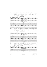
Write 1.000000 to TARE_VALUE: TARE_VALUE [31..0] <87 [31..0]>
iii.
Save the new pressure offset value to non-volatile memory if required and re-
lock the configuration data registers as described in section 4.4.1.
Alternatively, to set the pressure offset to the current value of the COMP_PRES
register:
iv.
Copy the current COMP_PRES register value to the TARE_VALUE register.
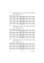
Write 0b1 to STATUS: SET_TARE <0 [11]>
To enable reading relative pressure:
v.
Enable the sensor tare mode.
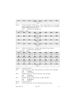
Write 0b1 to STATUS: TARE <0 [12]>
Pressure and temperature SNR
4.4.6
The DPS 5000 sensors provide compensated pressure and temperature readings
with a high SNR. However, for very low noise applications, the user can modify the
contents of the AVERAGE register to increase the SNR of either or both readings at
the expense of the sensor acquisition time.
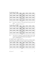
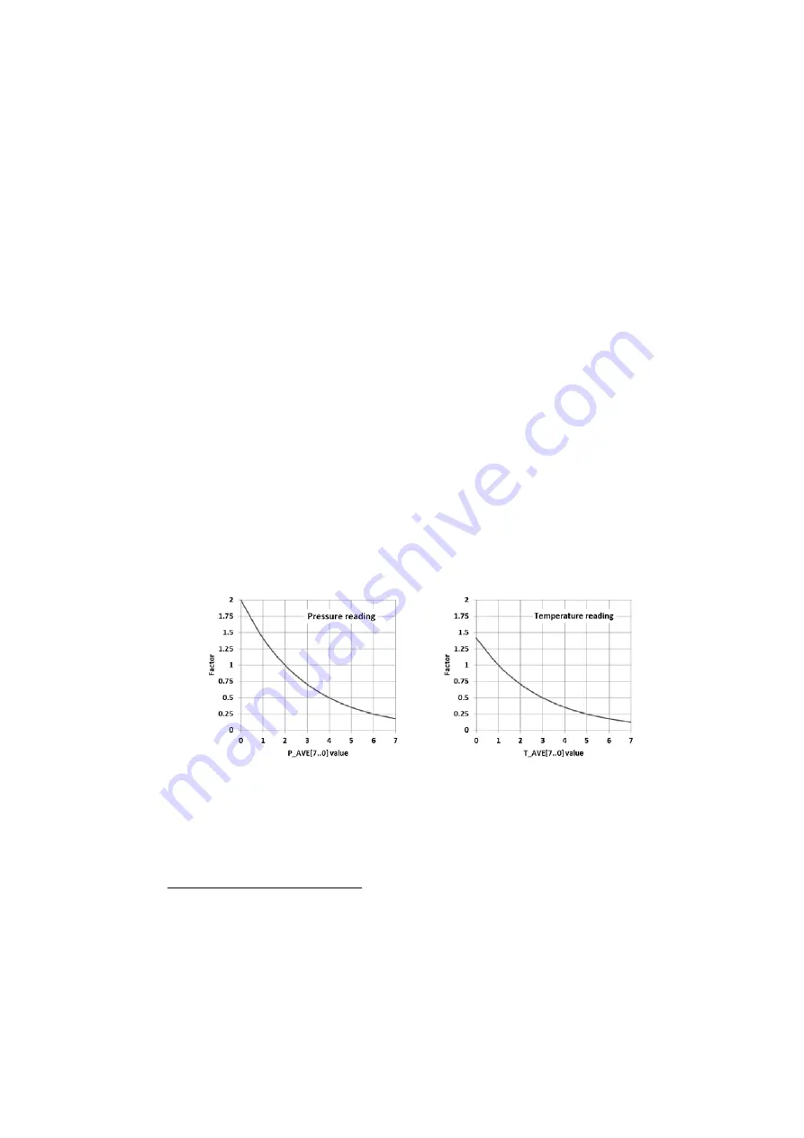
The AVERAGE register has 2 bit fields, P_AVE[7..0] and T_AVE[7..0] that can be used
to adjust the SNR of the pressure and temperature reading respectively. Typically
the sensors are supplied with P_AVE[7..0] set to 2 and T_AVE[7..0] set to 1. Modifying
these values will typically change the RMS amplitude of the corresponding reading
noise by the correction factor shown in Figure 8.
Figure 8 Noise level correction factors
If the values of the AVERAGE register P_AVE[7..0] and T_AVE[7..0] bit fields are
P
and
T
respectively, then the typical sensor acquisition time can be found using the
formula:
t
A
≈
2.12 ( 2
P
+ 2
T
) + 10.60 )
ms
11
11
This formula excludes the time taken to initiate a new data request when the sensor is used in the
manual mode as it is dependent upon the I
2
C-bus clock speed and the message length.


