5 Setups, alignments and adjustments
68
GE Healthcare
32551-IMG rev 6
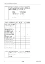
Fig 5.5.
C-arm display
5.2.7
Compression force and speed adjustment with ECS
NOTE!
The compression force is preadjusted at the factory and does not have to
be measured during the installation.
However, if the compression force needs to be changed, a bathroom
scale should be used. When using a bathroom scale, make sure that the
scale has soft material on top to simulate a more realistic compression.
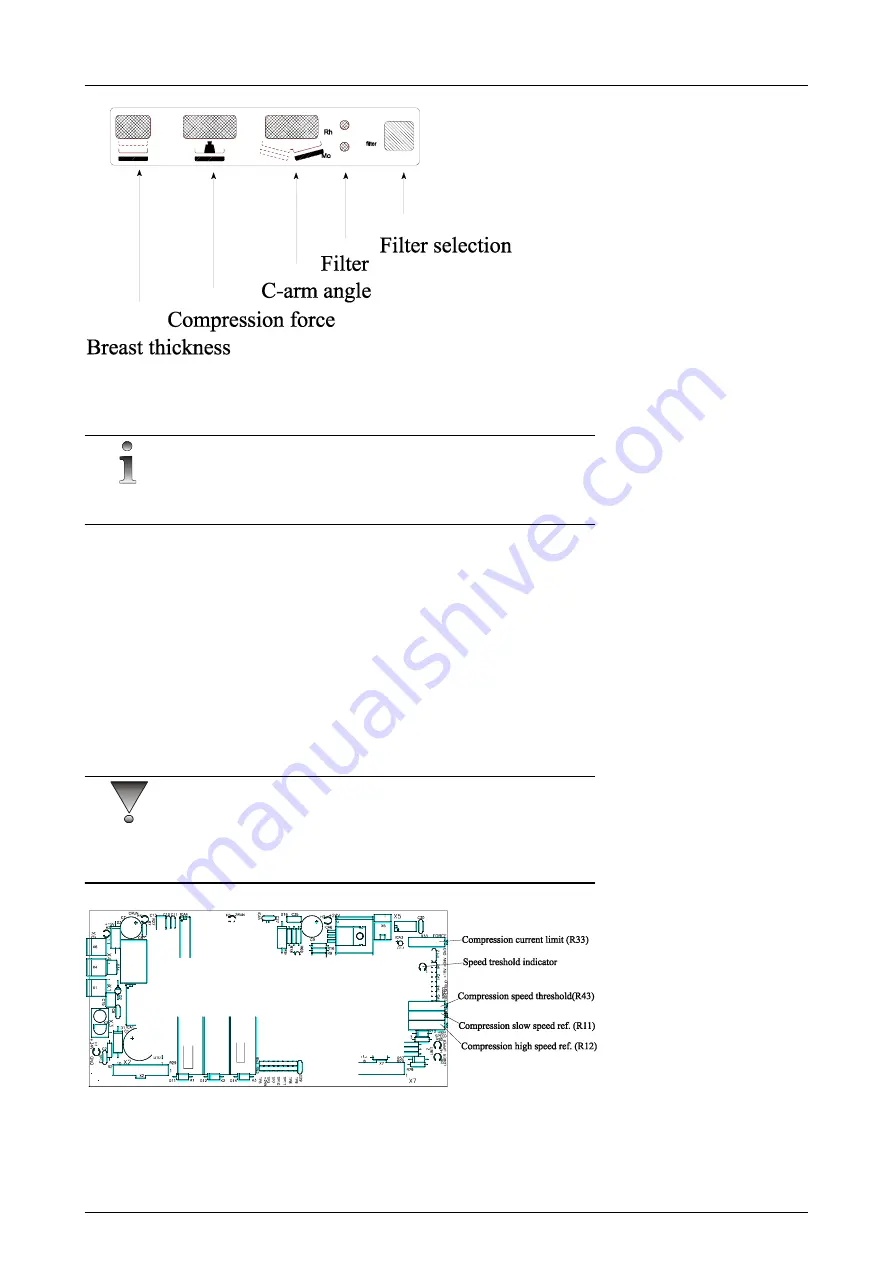
The electrical compression limit can be adjusted on the C&Z DRIVER
33035-IMG (see additional adjusting instructions in ECS manual 32921-
IMG).
User (major) adjustment is done by turning the external switch (the cable
coming to connector X5) in the front of the system. Minor adjustment can
be done by adjusting trimpot
R33
(clockwise to increase).
CAUTION!
When changing the maximum force, keep the external knob on maximum
position and when changing the minimum force, keep external knob on
minimum position.
Fig 5.6.
Adjustments on the C&Z Driver board 33035-IMG
Summary of Contents for Alpha RT 32551
Page 1: ...GE Healthcare Alpha RT Installation Instructions 32551 IMG rev 6 0459 ...
Page 2: ......
Page 4: ......
Page 42: ...3 Installation 36 GE Healthcare 32551 IMG rev 6 ...
Page 51: ...4 Alpha RT softstart procedure 32551 IMG rev 6 GE Healthcare 45 Fig 4 10 Inverter board ...
Page 52: ...4 Alpha RT softstart procedure 46 GE Healthcare 32551 IMG rev 6 ...
Page 71: ...5 Setups alignments and adjustments 32551 IMG rev 6 GE Healthcare 65 Fig 5 2 Magnetic brake ...
Page 94: ...5 Setups alignments and adjustments 88 GE Healthcare 32551 IMG rev 6 ...
Page 96: ...6 Alpha RT installation step by step 90 GE Healthcare 32551 IMG rev 6 ...
Page 97: ......
Page 98: ......

