background image

3  Installation

32551-IMG    rev 6

GE Healthcare

29

7

Attach the shield decal enclosed.

Both side installation:

Use the upper hinge bracket with hinges on both sides. Follow the

instructions given for left or right side installation.

Fig 3.13.

Left side installation

3.9

M

AINS


PLUG


INSTALLATION

The unit is delivered without mains plug attached to allow fitting of locally

suitable type of mains connection.

Select suitable min 16A rated mains plug (that complies with local

regulations) with ground (PE) connection. A loose IEC type plug is included

in the unit delivery.

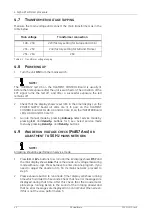
When connecting the wires, make sure that the yellow-green PE wire is

left min 10mm longer than the two other ones.

Summary of Contents for Alpha RT 32551

Page 1: ...GE Healthcare Alpha RT Installation Instructions 32551 IMG rev 6 0459 ...

Page 2: ......

Page 3: ...may not be copied photocopied reproduced translated or reduced to any electronic medium or machine readable form in whole or part without the prior written permission of GE Healthcare The original language of this manual is English General Electric Company reserves the right to make changes in specification and features shown herein or discontinue the product described at any time without notice o...

Page 4: ......

Page 5: ...tallation of the column to the wall 19 3 2 1 Attachment holes 19 3 2 2 Attachment of the column brackets 20 3 2 3 Lifting the column minimum 2 people 21 3 3 Installation of the column to the base plate 21 3 4 Localized unit label attachment 23 3 5 Installation of the c arm 24 3 5 1 Preparing the carriage 24 3 5 2 Preparing the C arm 24 3 5 3 Attaching the C arm 24 3 6 Attachment of the control pan...

Page 6: ...on 63 5 2 3 C arm brake adjustment 64 5 2 4 C arm angle display calibration Pr 54 Can 66 5 2 5 Compression force display calibration Pr 55 Cfo 66 5 2 6 Compression thickness display calibration Pr 56 Cth 67 5 2 7 Compression force and speed adjustment with ECS 68 5 2 8 The mechanical compression limit 71 5 2 9 kV mAs and exposure time test 73 5 2 10 Light field intensity adjustment 74 5 2 11 X ray...

Page 7: ...o jeopardizes patient operator and equipment safety WARNING This unit has floating grounds always make all scope measurements differentially and always be careful when servicing the unit CAUTION When handling circuit boards always utilize ground wrist straps or grounding kits to prevent damage to the mos type chips always keep circuit boards in a static proof bag WARNING Always disconnect the unit...

Page 8: ...e tank and high voltage connectors are dangerous areas in the that require special attention as well as 220 VAC present on Inverter Board AMD Board and fan connectors NOTE This unit has been tested at 60 Hz If the unit will be installed to 50 Hz mains network refer to Chapter 5 2 10 Light field intensity adjustment for collimator light field intensity adjustment and Chapter 4 9 Anode run voltage c...

Page 9: ...由客戶自行提供翻 譯服務 請勿試圖維修本設備 除非 您已查閱並瞭解本維修手冊 若未留意本警告 可能導致維修廠商 操作員或病患因觸電 機 械或其他危險而受傷 UPOZORENJE HR Ovaj servisni priručnik dostupan je na engleskom jeziku Ako davatelj usluge klijenta treba neki drugi jezik klijent je dužan osigurati prijevod Ne pokušavajte servisirati opremu ako niste u potpunosti pročitali i razumjeli ovaj servisni priručnik Zanemarite li ovo upozorenje može doći do ozljede davatelja u...

Page 10: ...iden dat het onderhoudspersoneel de operator of een patiënt gewond raakt als gevolg van een elektrische schok mechanische of andere gevaren WARNING EN This service manual is available in English only If a customer s service provider requires a language other than english it is the customer s responsibility to provide translation services Do not attempt to service the equipment unless this service ...

Page 11: ...άν ο τεχνικός σέρβις ενός πελάτη απαιτεί το παρόν εγχειρίδιο σε γλώσσα εκτός των αγγλικών αποτελεί ευθύνη του πελάτη να παρέχει τις υπηρεσίες μετάφρασης Μην επιχειρήσετε την εκτέλεση εργασιών σέρβις στον εξοπλισμό αν δεν έχετε συμβουλευτεί και κατανοήσει το παρόν εγχειρίδιο σέρβις Αν δεν προσέξετε την προειδοποίηση αυτή ενδέχεται να προκληθεί τραυματισμός στον τεχνικό σέρβις στο χειριστή ή στον ασ...

Page 12: ...s rokasgrāmata ir pieejama tikai angļu valodā Ja klienta apkopes sniedzējam nepieciešama informācija citā valodā klienta pienākums ir nodrošināt tulkojumu Neveiciet aprīkojuma apkopi bez apkopes rokasgrāmatas izlasīšanas un saprašanas Šī brīdinājuma neievērošanas rezultātā var rasties elektriskās strāvas trieciena mehānisku vai citu faktoru izraisītu traumu risks apkopes sniedzējam operatoram vai ...

Page 13: ...da responsabilidade do cliente fornecer os serviços de tradução Não tente reparar o equipamento sem ter consultado e compreendido este manual de assistência técnica O não cumprimento deste aviso pode colocar em perigo a segurança do técnico do operador ou do paciente devido a choques eléctricos mecânicos ou outros ATENŢIE RO Acest manual de service este disponibil doar în limba engleză Dacă un fur...

Page 14: ...esente aviso puede dar lugar a que el proveedor de servicios el operador o el paciente sufran lesiones provocadas por causas eléctricas mecánicas o de otra naturaleza VARNING SV Den här servicehandboken finns bara tillgänglig på engelska Om en kunds servicetekniker har behov av ett annat språk än engelska ansvarar kunden för att tillhandahålla översättningstjänster Försök inte utföra service på ut...

Page 15: ...hrough the mechanical installation one person thereafter 2 1 SPACE REQUIREMENTS The minimum space requirements and recommended free space around the unit are shown in figure 2 1 Space requirements Dimensions are in millimeters mm To convert to inches multiply given dimension by 0 0394 1mm 0 0394in Fig 2 1 Space requirements ...

Page 16: ...2VAC Line voltages measuring less than 208 VAC may require a line boost transformer Line Voltage 220 VAC nominal tap selection 220 240 or 260 VAC Line Regulation 2 full load Phase single phase Line Neutral Protective Ground or L1 L2 Protective Ground Frequency 50 60Hz Current stand by 1A maximum 20 A instantaneous peak 30 A Branch Circuit dedicated Line Neutral Protective Ground 2 5mm2 L1 and L2 1...

Page 17: ...ration in which it will be used Electrostatic discharges environment recommendations In order to reduce electrostatic discharges interferences the floor material shall be a dissipative material versus the electrostatic charge stacking The relative humidity shall be at least 30 percent The dissipative material shall be connected to the system ground reference Pins of connectors should not be touche...

Page 18: ...s from such transportation 2 9 UNPACKING THE UNIT The standard unit delivery comprises three four in base plate installation crates check that they have the same serial number of the following dimensions and with these contents NOTE The crate numbers in the packing list may differ from the numbers listed here Crate 1 2290 x 520 x 410 mm 90 3 16 x 20 1 2 x 16 3 16 cardboard gross weight approximate...

Page 19: ... crate 5 if ECS is not delivered with the unit 870 x 710 x 170 mm 34 5 16 x 28 x 6 11 16 wooden gross weight approximately 68 kg 150 lb base plate 2 10 UNPACKING THE COLUMN WITH THE CARRIAGE cut the packing straps unscrew Phillips screws open the fastened cover remove the supporting brackets by loosening the bolts outside the crate remove the cardboard box including wall mount installation kit rem...

Page 20: ...2 Preinstallation instructions 14 GE Healthcare 32551 IMG rev 6 Fig 2 2 Column with carriage NOTE The crate includes the packing list Make sure that you have received all items ...

Page 21: ...g bracket to the crate lift out the C arm remove the packing bracket from the C arm CAUTION The bolts holding the bracket are not meant to be used as attachment bolts they are too long Attachment bolts are supplied separately in a plastic bag Fig 2 3 C arm packing 2 12 UNPACKING THE COUNTERWEIGHT cut the packing straps unscrew Phillips screws open the fastened cover remove the spacing boards and l...

Page 22: ... or 220 lbs Get assistance to handle it and be extreme careful 2 13 UNPACKING THE ACCESSORIES cut the packing straps unscrew Phillips screws open the fastened cover 2 14 UNPACKING THE BASE PLATE cut the packing straps unscrew Phillips screws open the fastened cover remove the support pieces Fig 2 4 Base plate packing ...

Page 23: ...mn is lifted out it can immediately be risen into its final position 2 Lift the column out of the crate and rest it on the C arm crate with the center axle pointed to the bottom Be sure to set the column on some soft material to prevent scratches 3 Loosen the bolts holding the top cap in position See A in figure 3 1 Vertical motor and cables 4 Slide the top cap away from the column Check that the ...

Page 24: ...d 9 Install the mechanical stop 10 Connect the vertical motor cable 11 Install the top column cap 12 Slide the carriage down the column until the cables are taut 13 Verify that the assembly pin installed above is securely fastened to the column and cannot fall out 14 If wall installation kit is used go to 3 2 Installation of the column to the wall If the installation is done on a base plate go to ...

Page 25: ... used Each bolt should be able to take a load of 600 N 135 lbs Lift up the column against the wall and drill the holes like in figure 3 2 Wall attachment holes Long short column version Fix the enclosed plugs in the holes Fig 3 2 Wall attachment holes Long short column version 16 5 32 410 mm 2184 1969 mm 86 3 64 77 9 16 If no base plate then subtract 14 mm 9 16 ...

Page 26: ...hcare 32551 IMG rev 6 3 2 2 Attachment of the column brackets Attach the wall mount bracket and base plate to the column See figures 3 3 Wall mount bracket and 3 4 Base plate Fig 3 3 Wall mount bracket Fig 3 4 Base plate 400 220 ...

Page 27: ...t helps in installing the C arm by keeping the cables out of the way 3 3 INSTALLATION OF THE COLUMN TO THE BASE PLATE 1 Unpack the base plate and compare its contents to the packing list 2 Place the base plate in its final position so that the screw holes face to the rear of the unit 3 Bolt both side pieces to the base plate making sure they are centered over the bolt holes Trace the inside edge o...

Page 28: ... B is not symmetrical and should be installed so that its width matches the column width Also notice the slot for the cable 9 Tighten all bolts and check the column with a water level Shift the column if necessary and tighten slightly the four bolts for the pressure plate CAUTION Do not tighten the pressure plate too much since the counterweight might jam in the lower position Use for example 3 Nm...

Page 29: ...rom the release paper 1 Practice for correct alignment Localized text for Date of manufacture MODEL NO Model name and Ser NO and graphical symbols must be placed over the English original so that the unit specific data remain visible Illustration examples below are provided to guide the alignment and attachment Original unit main label Additional translated label 2 Remove the label from the releas...

Page 30: ...ure requires that the holes for these bolts are aligned If it is necessary to move the ECS mechanism to align these holes use a voltage supply for example a regular 9V battery to run the motor Be careful not to run the mechanism against either end 4 Make sure that the metal plate plate attached to the ECS mechanism is not bent or otherwise damaged 3 5 3 Attaching the C arm 1 Lift the C arm into po...

Page 31: ...ween the carriage and C arm according to their numbers X10 X11 X17 X18 X20 X61 6 Connectors AMD X1 AMD X2 and AMD X3 are attached to the anode motor driver AMD board inside the C arm X61 is only on Alpha RT models See Figure 3 8 C arm connectors NOTE X20 has 10 wires on the Alpha RT Fig 3 8 C arm connectors ...

Page 32: ...four bolts 10 Close the connectors to the c arm Check that the bracket relieves stress to the wires in the connectors See figure 3 9 Securing the cables to the c arm Fig 3 9 Securing the cables to the c arm 11 Make sure that the metal plate going through the slots of the optical interrupters on the ECS Driver Board is correctly positioned and that there are no cables entering its pathway when the ...

Page 33: ...ole in the base Use setscrews to fasten the panel to the base Also fasten the exposure button to its place with a setscrew if required Attach the cable of the panel to the D connector at the base of the carriage The control may be installed flat to the side of the carriage or to an angle with the angled back piece Fig 3 10 Control panel attachment ...

Page 34: ... crate and compare the contents to the packing list If the stationary base plate is used locate the hole provided for the hinge in base the plate Drop the sleeve in a hole mount Left or right side installation 1 Press the other plastic sleeve into the large hole on the upper hinge bracket 2 Screw the bracket with M6 screws 2 on top of the column 3 Put the lower hinge pin into the bottom sleeve 4 L...

Page 35: ... Left side installation 3 9 MAINS PLUG INSTALLATION The unit is delivered without mains plug attached to allow fitting of locally suitable type of mains connection Select suitable min 16A rated mains plug that complies with local regulations with ground PE connection A loose IEC type plug is included in the unit delivery When connecting the wires make sure that the yellow green PE wire is left min...

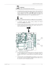
Page 36: ... the country code Resetting must be acknowledged by pushing the auto exp button which starts the internal testing routine 2 Check that all segments of the 7 segment display and LEDs are lit C arm display shows the software version of C arm control board 3 Install a cassette tunnel for normal film screen imaging corresponding diaphragm and a cassette Notice the cassette type Normal or Daylight Fig ...

Page 37: ...ndicate 12 mAs 9 Select 25 kV Using the mAs and mAs buttons increase the mAs value to 500 300 in New York installations 600 in G B installations and then decrease the display back down to 80 Go back to automatic exposure mode by using the auto exp button 10 Push the auto rel button twice The auto rel light should first switch off and then back on NOTE Press the vertical drive control down and remo...

Page 38: ...Fig 3 15 Location of the grid locking screw 15 Install a bucky and check that the GRID indicator lights up Remove the grid locking screw before use 16 Install a magnification table and check that the MAGN indicator lights up 17 Turn the c arm and notice that the reading in the angle display on the c arm changes CAUTION C arm brake can get stuck during the long storage time Press the brake button t...

Page 39: ... Unreg 34Vdc 33 Vdc TP7 to TP4 Vin CPU 23 Vdc TP7 to TP5 AEC in 20 Vdc TP7 to TP6 AEC in 20 Vdc TP8 to TP9 lamp AC volts 10 5 Vac CPU BOARD Code 32245 IMG across diode D3 Vin CPU 5 1 Vdc C Z BOARD Code 33035 IMG TP1 to TP12 Vin C Z 34 Vdc TP2 to TP12 15 Vdc TP3 to TP12 Vin bucky 24 Vdc TP4 to TP13 Comp low speed ref adjustable 15 Vdc TP5 to TP13 Comp high speed ref adjustable 15 Vdc TP8 to TP9 Com...

Page 40: ...ovement can be stopped by pressing the C arm up or C arm down buttons 6 When driven away from the lowest position check that the c arm brake does not release After returning the c arm check that the brake releases again 7 Check that the foot pedal works 8 Proceed the installation according to the Installation Instructions and return to the ECS installation after the Alpha RT installation is finish...

Page 41: ...ssion paddle speed adjust the ECS movement with R37 on ECS board 12 Press REL pedal to set movements to start position Press ECS pedal and adjust the speed from R37 until the dimension between floor level and compression paddle does not change 13 Press the C ARM pedal and adjust the C arm speed from R59 to about 1cm 1sec ...

Page 42: ...3 Installation 36 GE Healthcare 32551 IMG rev 6 ...

Page 43: ...ts are correct Use large focus MAGN lamp is off WARNING When installing or removing covers make sure that no articles such screws etc can fall through to the open spaces between the column and the carriage Serious problems for the use of the device may occur 4 2 REMOVAL OF THE SIDE COVERS 1 Remove the side and back covers to expose the circuit boards CAUTION Do not pull out the side cover just str...

Page 44: ...L OF THE TOP COVER 1 Remove the top cover of the C arm to expose the high voltage unit Fig 4 2 Removing the top cover by opening the four screws 4 4 REMOVAL OF THE BOTTOM COVER 1 Remove the bottom cover of the C arm to expose the high voltage unit Fig 4 3 Removing the bottom cover by opening the four screws ...

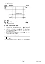
Page 45: ...re not allowed 1 Unplug connector X1 on the INVERTER Board a four pin connector 2 Set the test switches on both the INVERTER Board and the FILAMENT CONTROL Board to TEST position Set the jumper X8 on the FILAMENT CONTROL Board to 1 2 position left hand position mA feedback from the filament circuit only 3 On the FILAMENT CONTROL Board unplug the connector X4 power to the filament 4 Turn OFF the un...

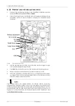
Page 46: ...mode menu by pressing Density and Density buttons 4 9 ANODE RUN VOLTAGE CHECK PR 57 ANO OR ADJUSTMENT TO 50 HZ MAINS NETWORK NOTE All testing should be performed in service mode 1 Press kV or kV buttons to scroll until the kV display shows 57 and the mAs display shows Ano This is the anode run voltage measuring mode without x rays Press Autoexp to enter into Ano program If you need to adjust the a...

Page 47: ...rent for 50 Hz and 60 Hz 4 If necessary adjust the anode running voltage with trimmer potentiometer R100 on AMD Board 5 Exit the test 57 and also the service mode Test the unit in normal manual mode with maximum mAs value repeat exposures for 5 times and verify that no error appears Fig 4 5 Anode motor drive board AMD 6 During the exposure listen that the first one of the power relays K1 on the IN...

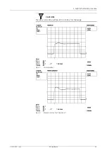
Page 48: ...age mode 4 Turn ON the unit Set the unit to 27kV and 16 40 mAs large focus 5 Make an exposure and check the waveform see Fig 2 28 6 If the mA waveform contains either over or undershoot at the start up adjust from trimmer potentiometer R28 on the Filament control board to obtain correct waveform NOTE The trimmer R28 is for LARGE FOCUS For SMALL FOCUS insert the magnification cassette holder to the...

Page 49: ...4 Alpha RT softstart procedure 32551 IMG rev 6 GE Healthcare 43 CAUTION Too slow a rise time will result in an E 01 error message Fig 4 7 Correct preheat Fig 4 8 Preheat rises too fast Overshoot ...

Page 50: ... the DVM to 0 10 Vdc range 2 Set the unit to 28kV and 100 mAs To get longer exposure time increase mAs Make sure that the exposure is long enough for the DVM reading to stabilize 3 Make an exposure and check the voltage from the DVM during exposure It should be 2 8 0 01Vdc 4 If not adjust from trimmer potentiometer R63 NOTE kV is set at the factory For calibration use Unfors RTI PMX I M or similar...

Page 51: ...4 Alpha RT softstart procedure 32551 IMG rev 6 GE Healthcare 45 Fig 4 10 Inverter board ...

Page 52: ...4 Alpha RT softstart procedure 46 GE Healthcare 32551 IMG rev 6 ...

Page 53: ... SUP i i o device 52 SUP F Default filter 53 PAr S The serial number of the unit 53 PAr C Country code 53 PAr r Tube efficiency in mR mAs for both filters 53 PAr b Anode brake selection 53 PAr t Software mode and Phototimer modes 53 PAr I Collimator type Interlock 53 PAr d C arm control board CD board selection 64 AEC d Wanted optical density 64 AEC h IQC kV programming 64 AEC I Target time MIN MA...

Page 54: ...sing AUTOEXP button NOTE See block diagram of software in appendix or service manual 5 1 2 Setup Info Printout and printer PC connection 62 InF Connect a matrix printer or a PC Laptop to Alpha RT com port Select service program 52SUP with the kV or kV buttons Enter the program pressing the Autoexp button Press Autoexp to exit program 52SUP Select service program 62Inf with the kV or kV buttons Pre...

Page 55: ...CONTACT Mo kV mAs kV mAs kV mAs 00027 00012 00027 00012 00027 00012 BUCKY Rh MAGN Rh CONTACT Rh kV mAs kV mAs kV mAs 00027 00012 00027 00012 00027 00012 USER DENSITY STEP 0 10 FULL AEC TARGET TIME variables limits BUCKY Mo 0 25 0 10 0 50 3 50 BUCKY Rh 0 25 0 10 0 50 3 50 MAGN Mo 0 25 0 30 0 50 5 00 MAGN Rh 0 25 0 30 0 50 5 00 CONTACT Mo 0 25 0 10 0 50 3 50 CONTACT Rh 0 25 0 10 0 50 3 50 THICKNESS ...

Page 56: ...itions 30 through 44 and row 4 positions 45 through 59 See following the ASCII table and a Label Programming Worksheet 52SUP A The density display shows A which means the Auto Release Time after each exposure in seconds 1 Select a suitable time normally 6 sec using the density and density buttons Make sure that after an exposure the Autorelease drives the paddle up to the upper limit 2 Press kV 52...

Page 57: ...2 ó 194 226 _ 3 ETX 35 67 C 99 c 131 â 163 ú 195 227 4 EOT 36 68 D 100 d 132 ä 164 ñ 196 228 _ 5 ENQ 37 69 E 101 e 133 à 165 Ñ 197 229 _ 6 ACK 38 70 F 102 f 134 å 166 0 198 _ 230 m 7 BEL 39 71 G 103 g 135 ç 167 1 199 _ 231 _ 8 BS 40 72 H 104 h 136 ê 168 200 232 _ 9 HT 41 73 I 105 I 137 ë 169 _ 201 233 _ 10 LF 42 74 J 106 j 138 è 170 5 202 234 _ 11 VT 43 75 K 107 k 139 ï 171 2 203 235 _ 12 FF 44 76...

Page 58: ...B 58 90 Z 122 z 154 Ü 186 _ 218 250 A 27 ESC 59 91 123 155 4 187 219 _ 251 _ 28 FS 60 92 124 156 188 220 _ 252 n 29 GS 61 93 125 157 189 221 _ 253 5 30 RS 62 94 126 158 P 190 222 _ 254 _ 31 US 63 95 _ 127 DEL 159 191 223 _ 255 SP Table 5 2 ASCII code and corresponding alphanumerical letter table Position 00 01 02 03 04 05 06 07 08 09 10 11 12 13 Text ASCII Position 14 15 16 17 18 19 20 21 22 23 24...

Page 59: ...This mode determines which filter type is selected in the power up Select the mode using the density and density keys 0 selects automatically the rhodium filter 1 selects automatically the molybdenum filter 2 selects the previously used filter 3 selects the auto filter mode Use mAs and mAs keys to determine the compression thickness 0 95 mm in kV display where the filter changes Press kV Press Aut...

Page 60: ...me position X Compression releasing is interrupted if compression force measurement fails X The compression will be automatically released 25 seconds after the exposure X X Maximum available voltage 34kV X IQC correction range 0 75 1 25 others 0 60 1 40 X Maximum exposure time 3s maximum mAs 300 mAs X Maximum exposure time 6s maximum mAs 600 mAs X If C arm brake is released the compression is rele...

Page 61: ...ress to the bearings Press kV 53PAr t The density display shows t In this mode the software for Alpha RT is selected 0 Not for Alpha RT 1 Not for Alpha RT 2 Only AA and manual mode Alpha RT 3 Only A and manual mode Alpha RT 4 AA A manual mode factory default Alpha RT 5 A AA manual mode Alpha RT Press kV 53PAr I Collimator type Interlock 1 for MGB 500 Collimator with interlock 0 for MGB 400 Collima...

Page 62: ...ensitometer and process the film Select the step that has the optical density close to 1 00 Program the O D into this mode Inform the technologist to follow this step when performing the IQC Refer to Operation Instructions Chapter Integrated Quality Control test IQC is done by making a test exposure with a phantom and with the kV selected for IQC see parameter h Program the wanted optical density ...

Page 63: ...default min 0 5 sec max 3 5 sec The kV display will show HI and LO respectively Use Den buttons to alter the value 2 Press kV 64AEC c The density display shows c This is for the AEC thickness compensation including five 5 subparameters P r1 r2 S1 S2 in kV display For further information on thickness compensation refer to section AEC adjustment Press kV 64AEC g The density display shows g This is t...

Page 64: ...ve the compression to 0 cm Driving the paddle up and down you cansee initial kV values for different thicknesses 4 Select the initial kV value for 0 cm with Density buttons 5 Drive the compression paddle up 0 5 cm and select the initial kV value with Density buttons 6 Repeat point 5 until you have programmed the initial kV for 9 5 cm 7 Install next cassette holder and repeat the kV programming 8 S...

Page 65: ... values Bucky default values Mo and Rh Magn new values Magn Default values Mo and Rh 0 0 23 23 25 0 5 23 23 25 1 0 23 23 25 1 5 23 23 25 2 0 23 23 25 2 5 23 23 25 3 0 23 23 25 3 5 24 24 25 4 0 24 24 26 4 5 24 24 26 5 0 25 25 26 5 5 25 25 27 6 0 26 26 27 6 5 26 26 28 7 0 27 27 28 7 5 27 27 28 8 0 28 28 29 8 5 28 28 29 9 0 28 28 30 9 5 28 28 30 Table 5 4 Initial kV table ...

Page 66: ...near curve calculated from two programmed points See a graph below 64AEC U The density display shows U In A and AA modes the parameter U enables the separate optical density corrections for the following for all kV steps within 20 35 kV for Molybdenum and Rhodium filter separately for Bucky Magnification and cassette holders separately The range for kV correction is 0 70 1 30 while the default val...

Page 67: ...ith Den buttons 4 Press Autorel The density display will show 2 T2 The kV display will show the current compression thickness Drive the compression plate to desired thickness for the second target time Alter the target time with Den buttons 5 Press Autorel The mAs display will show PAS or ERR depending on the programming being successful or not The density display shows 0 and the target times for ...

Page 68: ... shows the exposure counters and the error codes tot cnt E01 E02 E03 E04 E07 E08 E09 E10 E11 E12 Slo Er1 Er2 Er3 Er4 Er5 Eaf SYS The kV and mAs displays show the number of those errors Pressing the mAs resets the counter in the display Pressing the kV button selects the next counter Reset all the counters When the timer display shows tot the exposure counter is shown It cannot be reset The cnt cou...

Page 69: ...h would appear on your film 3 Obtain a sheet of the same film type to be used in your Alpha RT Select the color on the sensitometer that matches the color emitted by the intensifying screen used 4 Ensure that the emulsion side of the film is towards the light source on the sensitometer Expose two edges of the film waiting 10 seconds between exposures and run it through the processor 5 Measure and ...

Page 70: ...oc nuts 3 If the brake does not release properly open the nuts 1 and adjust the space 4 with the screws 2 The space should be about 0 1 to 0 4 mm CAUTION Make only minor adjustments of the nyloc nuts measured by the flats of the nuts Date Time Film type Water temp Dev temp Gross fog Speed index Contrast index Date Time Film type Water temp Dev temp Gross fog Speed index Contrast index Date Time Fi...

Page 71: ...5 Setups alignments and adjustments 32551 IMG rev 6 GE Healthcare 65 Fig 5 2 Magnetic brake ...

Page 72: ...the program menu is entered If the calibration is not correct the program is automatically returned to the beginning and the to 00 is displayed in the kV and mAs display Fig 5 3 C arm display 5 2 5 Compression force display calibration Pr 55 Cfo The compression force display can be calibrated with the special program 55 Cfo CAUTION Make sure that the c arm angle display is calibrated before calibr...

Page 73: ...s program the mAs display shows to 00 with bucky or to 20 with cassette tunnel 1 Drive the compression paddle completely down against the bucky cassette tunnel Press Autorel The 0 0 2 0 cm level is now programmed The control unit shows to 60 2 Place 60 mm acrylic on the Bucky cassette tunnel and drive the compression paddle down If you do not have 60 mm acrylic available the 60 mm display can be c...

Page 74: ...t material on top to simulate a more realistic compression The electrical compression limit can be adjusted on the C Z DRIVER 33035 IMG see additional adjusting instructions in ECS manual 32921 IMG User major adjustment is done by turning the external switch the cable coming to connector X5 in the front of the system Minor adjustment can be done by adjusting trimpot R33 clockwise to increase CAUTI...

Page 75: ...l compression wheels see also section 5 2 8 The mechanical compression limit Fig 5 8 Compression mechanism notice that compression force range should be 28 30 kg 62 66lbs B Adjustment of electrical max compression force limit trimmer R 33 board remove cable X4 from C arm board turn the compression force switch 1 6 to position six 6 turn trimpot R33 totally to zero totally counterclockwise place a ...

Page 76: ...sitions 1 6 according to desires of the customer If needed use customer s own reference when adjusting forces Adjust limit values to comply with reference system Compression minimum force limit is not recommended to adjust to be less than 8 kg 16lbs See appendix Software Block diagram Subparameter Meaning Manufacturer default setting default 0 compression limit mode 0 absolute limit default 1 comp...

Page 77: ... compression paddle does not change more than 2 cm 5 2 8 The mechanical compression limit The mechanical compression limit is set by adjusting the compression clutch The mechanical clutch is adjusted at the factory to stop the compression at 28 30kg 62 66lbs Do not readjust it unless needed Remove the plastic plug in the back cover of the C arm to reach the sealed and labeled set screw and make ad...

Page 78: ...5 Setups alignments and adjustments 72 GE Healthcare 32551 IMG rev 6 Fig 5 8 Compression mechanism Mechanical clutch adjustment Sliding bar clearance adjustment ...

Page 79: ...as shown in the table below and make the exposures 3 Record the kV mAs and time reading after each exposure The time reading is to be compared with the Alpha RT control panel time display The maximum tolerance for kV mAs and exposure time are For kV 1 5 kV instrument inaccuracy 1 5 kV 1 5 of reading 600V For mAs 4 mAs for mAs values less than or equal to 40 mAs 10 for mAs values greater than 40 mA...

Page 80: ...the amount of LUX ISLC s that local regulations require Take note of the effect of the examination room lighting unless it can be totally switched off The halogen lamp lifetime increases when lamp voltage is decreased and vice versa Fig 5 9 Supply board 5 2 11 X ray field alignment 1 Go into the service mode by pressing the kV and density buttons simultaneously and holding them until ser is displa...

Page 81: ...e light field alignment Place a loaded cassette in the holder and position the corresponding diaphragm 1 Go into the service mode by pressing the kV and density buttons simultaneously and holding them until ser is displayed on the timer display 2 Select manual mode at 25 kV and 20 mAs 3 Place a sheet of white paper on the cassette holder so that the light field can be seen clearly Place some coins...

Page 82: ...the bucky In the small bucky the grid should be at the bottom of the grid drive block groove and fastened with four set screws In the large bucky the grid should be fastened only with two set screws and aligned by the two rear set screws 2 Check that the grid doesn t touch the side lips of the bucky and that it is centered Check also that the grid is aligned parallel to the side lips Speed adjustm...

Page 83: ...nsitometer Acrylic blocks Film Cassette 1 Attach Bucky device 2 Press Den Den for 3 sec to enter program Pr mode CAUTION Store all default values in the tables on the next pages molybdenum filter and rhodium filter 3 Press Autoexp to AA mode and channel a Select Molybdenum filter 4 Select max kV change range of initial kV factory default 4 kV with kV and kV keys Value can be selected between 0 9 k...

Page 84: ...e internal density correction factor default value 1 00 with mAs and mAs keys 10 Press Autoexp to select channel b Repeat instructions in 10 11 Press Autoexp to select channel c Repeat instructions in 10 12 Press Autoexp to select manual mode Select default kV factory default 27 kV with kV keys and default mAs factory default 12 mAs with mAs and mAs keys 13 Press Autoexp Select Rhodium filter and ...

Page 85: ...ecrease the Target time values Low kVs yield long mAs O fl errors or white images Start kV too low and or maximum allowable kV change too small Change the full AEC kV table Pr 64 AEC parameter E or Increase the kV change value Pr mode EAf errors Poor connection between CPU and AEC boards Incorrectly adjusted AEC offset voltages Check the cabling Adjust the AEC board offset voltages EAf error at st...

Page 86: ...y AA Mo 1 4kV a C hold AA Mo 1 4kV b C hold AA Mo 1 4kV c C hold AA Mo 1 4kV a Mag AA Mo 1 4kV b Mag AA Mo 1 4kV c Mag AA Mo 1 4kV a Bucky A Mo 27kV 1 b Bucky A Mo 27kV 1 c Bucky A Mo 27kV 1 a C holder A Mo 27kV 1 b C holder A Mo 27kV 1 c C holder A Mo 27kV 1 a Mag A Mo 27kV 1 b Mag A Mo 27kV 1 c Mag A Mo 27kV 1 manual mode Bucky Mo 27kV 12mAs manual mode Cassette holder Mo 27kV 12mAs manual mode ...

Page 87: ...y AA Rh 1 4kV a C hold AA Rh 1 4kV b C hold AA Rh 1 4kV c C hold AA Rh 1 4kV a Mag AA Rh 1 4kV b Mag AA Rh 1 4kV c Mag AA Rh 1 4kV a Bucky A Rh 27kV 1 b Bucky A Rh 27kV 1 c Bucky A Rh 27kV 1 a C holder A Rh 27kV 1 b C holder A Rh 27kV 1 c C holder A Rh 27kV 1 a Mag A Rh 27kV 1 b Mag A Rh 27kV 1 c Mag A Rh 27kV 1 manual mode Bucky Rh 27kV 12mAs manual mode Cassette holder Rh 27kV 12mAs manual mode ...

Page 88: ...arameter g is set to 1 00 2 Go back to service mode and make an exposure with semiautomatic A mode 28kV Molybdenum filter 40 mmAcr Use a compression paddle and a Bucky with a loaded cassette in it Detector must be in center position C1 Also remember to place the white plastic cover before exposure Fig 5 13 Placement of the acrylics and phantoms onto the cassette holder 3 Press Autorel after the ex...

Page 89: ...eter Also the exposure time is shown in the timer display for example 315 315 ms 1 54 1 54 sec 5 2 16 Adjusting the optical density O D 1 Reload the cassette with a new film and make a new exposure with the clinical kV for example 26kV Develop the film and mark the optical density of the film O D to the graph next page 2 Alter the AEC Gain parameter g in the service program 64 to 1 10 reload the c...

Page 90: ...mmAcr and measure the O D to check the adjustment Make note of the exposure time for the thickness compensation in the next section Exposure time _______________ CAUTION The AEC Gain g parameter will affect all exposures regardless of used filter or cassette holder 6 Make three exposures with different phantom thicknesses for example 20mm 40mm 60mm to get short medium and long exposure time and re...

Page 91: ...Den This is the exposure time which is not affected by thickness compensation the rotation point 6 Press Autorel to scroll the r1 parameter in the kV display Use Den buttons to change the value This parameter gives the amount of rotation at exposure times shorter than the rotation point P For example if the short exposure has 12 too dark a density enter 0 88 for r1 7 Press Autorel for the r2 param...

Page 92: ...arameter c is reached 12 Press Autorel to scroll the S1 parameter in the kV display Use Den buttons to change the value This parameter affects the compensation slope at exposures shorter than rotation point P 13 Press Autorel to scroll the S2 parameter in the kV display Use Den buttons to change the value This parameter affects the compensation slope at exposures longer than rotation point P 5 2 1...

Page 93: ...Den keys Repeat until the O D is correct 4 Mark the density value that produces the right optical density in the table 2 9 or 2 10 and store the values by programming them in the program Pr mode If the film screen combination and default kV is the same for all channels a b and c the density correction is the same also 5 Install the magnification tunnel 6 Repeat the instructions 3 and 4 7 Change th...

Page 94: ...5 Setups alignments and adjustments 88 GE Healthcare 32551 IMG rev 6 ...

Page 95: ...r the IQC See section Pr 64 AEC parameters d h and Operation Instructions section INTEGRATED QUALITY CONTROL TEST 5 Go into A mode Install the magnification kit Make an exposure with 40mm acrylic using 30 kV or a clinical kV at that thickness Process the film and measure the optical density if the optical density is too high select density until the wanted optical density is reached if the optical...

Page 96: ...6 Alpha RT installation step by step 90 GE Healthcare 32551 IMG rev 6 ...

Page 97: ......

Page 98: ......

Page 99: ... by General Electric Company Inc All rights reserved GE Hungary Kft a General Electric company going to market as GE Healthcare World Headquarters GE Healthcare P O Box 414 Milwaukee Wisconsin 53201 U S A European Headquarters GE Healthcare Europe Paris France Fax 33 1 30 70 94 35 Asia Pacific GE Healthcare Asia Tokyo Japan Fax 81 425 85 5490 Hong Kong Fax 852 2559 3588 www gehealthcare com Alpha ...

Reviews: