GE Allegro 60-874-95R User Manual Download Page 2

FCC Notices

FCC Part 15 Information to the User

Changes or modifications not expressly approved by GE Interlogix can void the user’s authority to operate the equipment.

FCC Part 15 Class B

This equipment has been tested and found to comply with the limits for a Class B digital device, pursuant to part 15 of the FCC Rules. These limits are designed 

to provide reasonable protection against interference in a residential installation.

This equipment generates, uses, and can radiate radio frequency energy and, if not installed and used in accordance with the instructions, may cause harmful 

interference to radio communications. However, there is no guarantee that interference will not occur in a particular installation.

If this equipment does cause harmful interference to radio or television reception, which can be determined by turning the equipment off and on, the user is 

encouraged to try to correct the interference by one or more of the following measures:

Reorient or relocate the receiving antenna.

Increase the separation between the equipment and receiver.

Connect the affected equipment and the panel receiver to separate outlets, on different branch circuits.

Consult the dealer or an experienced radio/TV technician for help.

FCC ID: B47-785B-ALGRO

ACTA Part 68

This equipment complies with Part 68 of the FCC Rules. Located on this equipment is a label that contains, among other information, the FCC registration num-

ber and the ringer equivalence number (REN) for this equipment. If requested, this information must be provided to the telephone company.

FCC Part 68 Registration No. B4Z-A101B46059 

The REN is used to determine the maximum number of devices that may be connected to your telephone line. Excessive RENs on a telephone line may result in 

devices not ringing in response to an incoming call. In most areas, the sum of all device RENs should not exceed five (5.0). To be certain of the number of 

devices that may be connected to a line, as determined by the total RENs, contact the local telephone company. For products approved after July 23, 2001, the 

REN for this product is part of the product identifier that has the format US:AAAEQ##TXXXX. The digits represented by ## are the REN without a decimal 

point (e.g., 03 is a REN of 0.3). For earlier products, the REN is separately shown on the label.

A plug and jack used to connect this equipment to the premises wiring and telephone network must comply with the applicable FCC Part 68 rules and require-

ments as adopted by ACTA. A compliant telephone cord and modular plug is provided with this product. It is designed to be connected to a compliant modular 

jack that is also compliant. See the Installation Instructions for details.

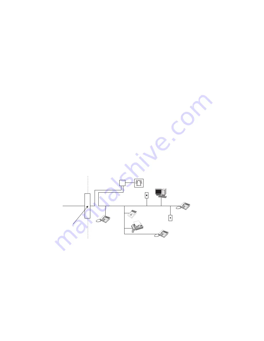
Alarm dialing equipment must be able to seize the telephone line and place a call in an emergency situation. It must be able to do this even if other equipment 

(telephone, answering system, computer modem, etc.) already has the telephone line in use. To do so, alarm dialing equipment must be connected to a properly 

installed RJ31X jack that is electrically in series and ahead of all other equipment attached to the same telephone line. Proper installation is depicted in the fol-

lowing diagram. If you have any questions concerning these instructions, consult your local telephone company or a qualified installer about installing an RJ31X 

jack and alarm dialing equipment for you.

If this equipment causes harm to the telephone network, the telephone company may temporarily disconnect your service. If possible, you will be notified in 

advance. When advance notice is not practical, you will be notified as soon as possible. You will also be advised of your right to file a complaint with the FCC.

The telephone company may make changes in its facilities, equipment, operations, or procedures that could affect the operation of the equipment. You will be 

given advance notice in order to maintain uninterrupted service.

If you experience trouble with this equipment, please contact the company that installed the equipment for service and/or repair information. The telephone com-

pany may ask you to disconnect this equipment from the network until the problem has been corrected or you are sure that the equipment is not malfunctioning.

This equipment may not be used on coin service provided by the telephone company. Connection to party lines is subject to state tariffs.

N e t w o r k

S e r v i c e

P r o v i d e r ' s

F a c i l i t i e s

T e l e p h o n e

L i n e

N e t w o r k

D e m a r c a t i o n

P o i n t

T e l e p h o n e

A n s w e r i n g

S y s t e m

F a x   M a c h i n e

C o m p u t e r

T e l e p h o n e

T e l e p h o n e

A l a r m   D i a l i n g

E q u i p m e n t

R J 3 1 X

J a c k

U n u s e d

R J - 1 1   J a c k

U n u s e d

R J - 1 1   J a c k

C u s t o m e r   P r e m i s e s   E q u i p m e n t   a n d   W i r i n g

Summary of Contents for Allegro 60-874-95R

Page 1: ...g GE Interlogix User Guide 466 1822 Rev C February 2003 Allegro Part No 60 874 95R www GE Interlogix com ...

Page 2: ... label A plug and jack used to connect this equipment to the premises wiring and telephone network must comply with the applicable FCC Part 68 rules and require ments as adopted by ACTA A compliant telephone cord and modular plug is provided with this product It is designed to be connected to a compliant modular jack that is also compliant See the Installation Instructions for details Alarm dialin...

Page 3: ...al Alarms 3 Aborting Accidental Alarms 3 Guidelines for Preventing Accidental Alarms 4 Panic Alarms 4 Police Panic Alarm 4 Fire Panic Alarm 5 Basic System Operations 5 Arming and Disarming Your System 5 Arming Level 1 Disarmed 6 Arming Level 2 Doors and Windows 6 Arming Level 3 Doors Windows and Motions 7 Arming Options 7 Quick Arm 7 Keychain Touchpad Arming 7 Quick Exit 8 Chime Feature 8 Exit and...

Page 4: ...ouble Beeps and Trouble Messages 14 Silencing Trouble Beeps 15 Cleaning the Panel 15 Appendix A Troubleshooting 16 Appendix B User Reference 18 System Information 18 User Codes 18 Keychain Touchpads 18 Accidental Smoke and Fire Alarms 18 Dialer Delay 18 Entry and Exit Delay Time Settings 18 Automatic Phone Test 19 Sensor Log 19 If the Power Goes Out 20 Conditions Displays and Sounds 20 Siren 22 Tr...

Page 5: ...ral station in an alarm situation The panel has a touchpad for arm ing disarming checking status and entering data such as access codes The DTIM The Dialog Telephone Interface Module DTIM provides added security by separat ing the telephone interface from the panel If the panel is damaged by fire or a break in it still reports to the central monitoring station Door Window Sensors Door and window s...

Page 6: ...panic alarm Note The Keychain Touchpad has not been investigated by UL Beeps and LEDs How Your System Talks to You The panel siren produces a variety of operating beeps to inform you of different system states and operations Key Beeps A key beep is the tone you hear when you press a button on the panel or handheld wireless touch pad The sound confirms that the button was adequately pressed Status ...

Page 7: ...ng the system or upon returning before disarming the system If for example you arm the system then run to another room for something you forgot the Exit Delay time may expire Once the Exit Delay expires opening an armed door or moving in front of an armed motion detector will cause an alarm or start the entry delay Aborting Accidental Alarms Your system can be set up with the opportunity to abort ...

Page 8: ...y guess causing alarms when you are away Check the location of your smoke detectors Smoke detectors near bathrooms can be tripped by steam from a shower Smoke detectors near the kitchen can be tripped by excessive smoke from cooking Panic Alarms Panic alarms are easily activated from any touchpad to quickly alert the central monitoring sta tion to a Fire or Police emergency A panic alarm can be se...

Page 9: ...these different needs By arming your system to a particular level only those sensors programmed to detect in that arming level will report alarm conditions to the panel 7 Table 4 Basic Panel Operating Commands How to Command Check system status Press once Disarm Arms doors and windows Arms doors and windows no delay Arms motions doors and windows Arms motions doors and windows no delay Arms system...

Page 10: ...tal alarm Disarming the system turns off any sirens when an alarm condition occurs To disarm to Level 1 using the panel keypad 1 Press once The panel displays Enter Code TO DISARM 2 Enter your access code The panel displays the current time and the system sounds one beep To disarm to Level 1 using a keychain touchpad Press the button To disarm to Level 1 using a wireless touchpad 1 Press the DISAR...

Page 11: ...vel 3 1 Close all perimeter doors and windows 2 Press twice The panel displays Enter Code TO ARM 3 Enter your access code The panel displays EXIT TIME XX and Motion Sensors Doors and Windows The system sounds three short beeps 4 Exit through a designated delay door before the delay time expires Note See Keychain touchpad arming section for other arming options To arm to Level 3 using a keychain to...

Page 12: ...ming the system to leave the premises through a designated delay door Entry Delay is the period of time you have to disarm the system after you open a designated delay door Exit Delay Example You re about to go on an errand You are inside your house and have just armed the system to Level 3 The panel siren sounds three quick status beeps telling you that the system accepted the com mand and has st...

Page 13: ...u re staying at home after you ve armed the system When you re arming your house from the outside You must have an installer programmed keychain touchpad with Keychain Touchpad Arm set to on in order to do this Arming to Level 2 or 3 with no delay using the panel keypad Note If Quick Arm feature is on an access code is not required 1 Close all perimeter doors and windows 2 Press once or twice 3 En...

Page 14: ...mode 1 Close all doors and windows 2 Arm your system to the desired level 3 Press Bypass The panel displays Enter Code TO BYPASS 4 Enter your primary access code The panel displays the sensors that are active in that level and can be bypassed in the system 5 Use the and to scroll through the listed sensors 6 Press Select to select the sensor to be bypassed Note Heat smoke carbon mon oxide and DTIM...

Page 15: ...ree beeps for Level 3 Note If all troubles have been resolved press Status twice to clear alarm memo ries The panel displays the following status information Alarm memory events following the disarming of the panel Abnormal sensor conditions open bypassed supervisory condition low battery or trouble System troubles are displayed If there are no current troubles alarms or events in alarm memory the...

Page 16: ... and then press To program change user 2 4 code Note The system will not accept the same code for two differ ent user codes 1 Press once and then until the desired user code is reached 2 Press to display the current user 2 4 code if any 3 Enter the desired user code and then press To delete a user code 1 Press once and then until you reach the desired code you want to delete 2 Press twice to erase...

Page 17: ...ed safeguard Taking time to do these tests will familiarize you with your system and alert you to anything unusual such as sen sors that have been tampered with Sensor Test This test verifies that the sensors in your system are operating correctly We recommend that you test sensors zones once weekly DTIM and battery tests are performed at the start of the sensor test The panel will display the DTI...

Page 18: ...e a downloader session enter your primary access code Trouble Beeps and Trouble Messages When your system detects a problem it lets you know by sounding trouble beeps from panel and by displaying status messages on the panel display see Appendix B Table 6 Sensor Tripping Instructions Sensor Do This Number of Beeps DTIM Initiate a sensor test 7 8 Door Window Open the secured door or window 7 8 Carb...

Page 19: ...cted trouble beeps and messages will restart 4 hours if fire related to10 hours if non fire related later Cleaning the Panel When your panel needs cleaning use a soft cloth glass cleaner or mild soapy water Spray the glass cleaner on the soft cloth or slightly dampen it with the soapy water and gently wipe clean the panel display Do not spray the glass cleaner on the display or let any liquid run ...

Page 20: ...anyone has had access to it Arming Disarming System protests and will not immediately arm 1 Make sure all monitored perimeter doors and windows are closed 2 Make sure all perimeter and interior sensors are closed 3 Press STATUS for an indication of the problem 4 If problem cannot be fixed the sensor may be temporarily bypassed see bypass section 5 Contact your installer dealer Bypassing Sensor to ...

Page 21: ... battery Replace battery if necessary 2 Contact your installer dealer Touchpad reports trouble condition 1 Check the touchpad battery for low voltage Replace battery if necessary 2 Contact your installer dealer if necessary Panel Tamper Touchpad reports Panel or Phone Module tamper 1 Verify that the Panel or Phone Module cover is closed Trouble Beeps Panel sounds 4 short beeps every minute 1 A tro...

Page 22: ..._______________ Dialer Delay Note Fire alarm reports to the central station cannot be aborted Is the Dialer Delay feature enabled Yes I have ____ seconds to abort an accidental intrusion or emergency alarm before it is reported to the central station No All alarms are reported to the central station immediately Entry and Exit Delay Time Settings Entry Delay Time ____________________ The time allow...

Page 23: ...ime the Exit Extension will begin No If I re enter the armed premises during the Exit Delay time it will continue to count down and I must disarm the system Keychain Touchpad Arm Yes Press the LOCK button to arm the system directly to Level 3 with No Delay No Each key press increments the arming level Auto Stay Arm Yes If after arming to Level 3 Door Windows and Motions I don t exit through a desi...

Page 24: ... Sensor Type Sensor Group Table B6 Normal Mode Condition Visual Display Audible Response Alarms Police Alarm POLICE then Alarm sensor name High level on steady tone Fire Alarm FIRE then Alarm sensor name Repeating series of three beeps Chime Alternates Chime On current time Beeps twice Silent Current time None Note 1 If there is both a Fire and Police Alarm the panel will display Alarm FIRE and th...

Page 25: ...rt beep then repeated Waiting for access code before entering user programming mode Enter Code FOR SETTINGS Alarm report aborted ABORTED Alarm report canceled CANCELED Sensors touchpads other devices status Sensor closed okay None Restoral required sensor open Press Status Open sensor name Restoral required sensor tamper open Press Status Open Trouble sensor name Bypassed sensor Press Status Bypas...

Page 26: ...ps will not occur between 10 p m and 8 a m Beeps in Level 1 or 2 for the following conditions Low CPU Battery Sensor Supervisories or Troubles Sensor Low Battery RF Jam RF Trouble Phone Module Failure System Memory Failure Table B7 Volume Level and Pattern Action Volume Level Pattern Entry delay Programmed Level One beep every 4 seconds last 10 seconds 1 beep every second If Alarmed Three beeps ev...

Page 27: ...e to warn for a variety of reasons If sirens are not placed within range of persons sleeping in remote areas of the premises or if they are placed behind doors or other obstacles If intruders gain access through unprotected entry points or areas where sensors are bypassed If intruders have the technical means of bypassing jamming or disconnecting any or all parts of the system If power to sensors ...

Page 28: ...d r o o m B e d r o o m D i n i n g R o o m K i t c h e n T V R o o m H N O T E D o n o t i n s t a l l s m o k e d e t e c t o r s w h e r e n o r m a l a m b i e n t t e m p e r a t u r e s a r e a b o v e 1 0 0 F o r b e l o w 4 0 F A l s o d o n o t l o c a t e d e t e c t o r s i n f r o n t o f A C H e a t r e g i s t e r s o r o t h e r l o c a t i o n s w h e r e n o r m a l a i r c i r c ...

Page 29: ...rence This device must accept any interference that may be received including interference that may cause undesired operation Changes or modifications not expressly approved by GE Interlogix Inc can void the user s authority to operate the equipment Patent Numbers 4 855 713 and 4 864 636 UL 1023 Household Burglary Warning System Control Unit Grade A ...

Page 30: ...26 ...

Page 31: ...27 ...

Page 32: ...rth Saint Paul MN 55109 g GE Interlogix 2003 GE Interlogix Allegro and Dialog are trademarks of GE Interlogix ToolBox is a registered trademark of GE Interlogix All other trademarks are properties of their owners All rights reserved ...

Reviews: