background image

7

Wiring

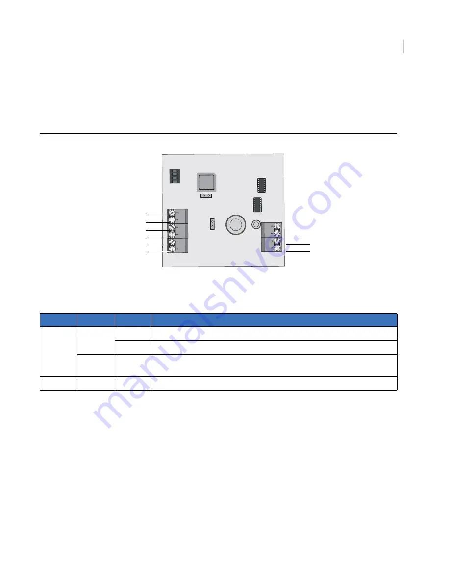
Wire the DGP terminals as shown in 

Figure 4

. Earth wires from all pieces of equipment must be grounded at 

one system earth. For more information on grounding details, refer to the Alliance control panel’s installation 
instructions.

Figure 4. Wiring diagram

Table 1

 shows the DGP wiring terminal details. 

DGP to Alliance control panel wiring restrictions

You can locate the DGP up to 5,000 feet (1.5 km) from the Alliance control panel. The DGP must be connected 
via a 2-pair twisted, shielded data cable from the system bus connection. We recommend you use  Belden 
8723.

Where the DGP power supply source is at a distance greater than 328 feet (100 m), you must use an external 
supply. We recommend a supply output of 13.8 VDC 1 A fused.

Table 1.

Wiring terminals

Connector Category

Terminals

Description

CON 1

COMMS

+, -

12 VDC power supply.

D+, D-

Positive and negative connection of the system bus.

TAMP

Ti, Tc

Connect the enclosure tamper switch across these terminals. Requires closed loop 
tamper switch.

CON 2

PID

+, -

9.9 to 13.2 VDC power supply. 

12

3

4

ON

-
-
+
+

+
-
D+
D-
Ti
Tc

CON 2

CON 1

JP1 TERM

JP2 LRN 

Summary of Contents for AL-1291 Point ID

Page 1: ...imagination at work GE Security AL 1291 Point ID DGP Installation Manual ...

Page 2: ...ames and addresses of actual businesses or persons is entirely coincidental Trademarks and patents GE and the GE monogram are registered trademarks of General Electric Other trade names used in this document may be trademarks or registered trademarks of the manufacturers or vendors of the respective products Intended use Use this product only for the purpose for which it was designed refer to the ...

Page 3: ...ssing our online publication library Note A qualified service person complying with all applicable codes should perform whatever hardware installation is required Conventions used in this document The following conventions are used in this document Safety terms and symbols These terms may appear in this manual Cautions identify conditions or practices that may result in damage to the equipment or ...

Page 4: ... at a distance of up to 5 000 feet 1 5 km from the control panel Product contents Each AL 1291 Point ID DGP ships with the following 2 three position terminal blocks 1 four position terminal block 4 clip in standoffs 4 mounting screws Inspect the package and contents for visible damage If any components are damaged or missing do not use the unit contact the supplier immediately If the unit needs t...

Page 5: ...rminal blocks together 2 Slide the terminal blocks over the pins on the board Figure 2 Figure 2 Exploded view CAUTION You must be free of static electricity before handling circuit boards Wear a grounding strap or touch a bare metal surface to discharge static electricity DIP switches CON 1 COMMS TAMP terminal block CON 2 point ID terminal block CON 10 EARTH LEDs ...

Page 6: ...n the enclosure using four clip in standoffs and mounting screws 5 Wire the unit to the system data bus and to point ID devices see Wiring on page 7 1 2 3 4 DGP 1 ON 1 2 3 4 DGP 2 ON 1 2 3 4 DGP 3 ON 1 2 3 4 DGP 4 ON 1 2 3 4 DGP 5 ON 1 2 3 4 DGP 6 ON 1 2 3 4 DGP 7 ON 1 2 3 4 DGP 8 ON 1 2 3 4 DGP 9 ON 1 2 3 4 DGP 10 ON 1 2 3 4 DGP 11 ON 1 2 3 4 DGP 12 ON 1 2 3 4 DGP 13 ON 1 2 3 4 DGP 14 ON 1 2 3 4 ...

Page 7: ...he DGP must be connected via a 2 pair twisted shielded data cable from the system bus connection We recommend you use Belden 8723 Where the DGP power supply source is at a distance greater than 328 feet 100 m you must use an external supply We recommend a supply output of 13 8 VDC 1 A fused Table 1 Wiring terminals Connector Category Terminals Description CON 1 COMMS 12 VDC power supply D D Positi...

Page 8: ...X The RX LED flashes to indicate polling data is being received by the point ID DGP from the Alliance control panel If the RX LED does not flash the DGP is not operational or the system bus is faulty Check the cabling TX The TX LED flashes to indicate the point ID DGP is replying to polling from the Alliance control panel If the RX LED flashes but the TX LED does not flash the DGP is not programme...

Page 9: ...device Be sure to take the 8 zone requirement into account when addressing the 4I4O devices For example if a 4I4O device is the first device you add to point ID DGP 1 it will be address 0 and the next device you add will be address 8 Table 3 Device addresses and related zone numbers DGP Zones Point ID address DGP Zones Point ID address Control panel 1 to 16 None DGP 8 129 to 144 0 to 15 DGP 1 17 t...

Page 10: ...1 ON 1 2 3 4 5 6 7 8 Point ID device 12 ON 1 2 3 4 5 6 7 8 Point ID device 13 ON 1 2 3 4 5 6 7 8 Point ID device 14 ON 1 2 3 4 5 6 7 8 Point ID device 15 ON 1 2 3 4 5 6 7 8 Point ID device 16 ON 1 2 3 4 5 6 7 8 Point ID device 17 ON 1 2 3 4 5 6 7 8 Point ID device 18 ON 1 2 3 4 5 6 7 8 Point ID device 19 ON 1 2 3 4 5 6 7 8 Point ID device 20 ON 1 2 3 4 5 6 7 8 Point ID device 21 ON 1 2 3 4 5 6 7 8...

Page 11: ...d press Enter 7 Enter the address number for the point ID DGP and press Enter The following programming menus are available and explained in detail in this section 1 DGP status 2 Device status 3 Device settings 4 Reset settings 5 Learn mode 6 DGP mode 7 Factory defaults Use the navigation tools shown in Table 4 to access the programming options Table 4 Programming navigation tools Key Description ...

Page 12: ... DGP Tamper Figure 8 Operational status Number and status of devices Figure 9 shows the number of devices known to the system the number of devices in alarm and the number of devices that have a tamper status Figure 9 Number and status of devices Input and output range Figure 10 shows the DGP number with the associated zone input and relay output numbers Figure 10 Input and output range Voltage su...

Page 13: ...dicates the device holds settings other than the defaults To scroll through the list press ENTER To get status information for a specific device enter the device zone input number and press ENTER Figure 14 Device list 3 Figure 15 shows the status for the device Devices not known learned to the system will show as Not Used When devices share the same address by mistake the status will read Multiple...

Page 14: ...r to access the device settings menu Figure 16 or if you do not need to use this menu press Enter to scroll to 4 Reset settings menu on page 17 Figure 16 Device settings menu 2 Figure 17 shows the zone number point ID address device category and device type for the first device on the list To scroll through the list press Enter To access programming locations for a specific device enter the device...

Page 15: ... indicates that all zone types are set to 10 double EOL To change the default change the 2 digits assigned to the zone type in the binary code For example reading the binary code from right to left bits 0 to 7 the last two digits on the left indicate the setting for zone type 4 If you need zone type 4 set to 01 single EOL change the binary code to 01101010 You can change as many of the zone types ...

Page 16: ...to 0 disabled change the binary code to 00001110 Location 6 Location 6 is reserved for future programming options Press Enter to scroll to the next location Location 7 Location 7 is reserved for future programming options Press Enter to scroll to the next location Location 8 Location 8 is a read only location that indicates the EOL end of line value The default setting is 47K which has a binary va...

Page 17: ...egory and device type for the first device on the list To scroll through the list press Enter To reset the settings for a specific device enter the device zone input number and press Enter Figure 20 Device list 3 Press the key to confirm the reset request When settings are unknown all values will be set to 10 Figure 21 Figure 21 Confirm reset 1 Enter 5 and press Enter to access the learn mode menu...

Page 18: ...uts 1 DGP plus expansion Allows for a total of 32 zones inputs and 16 relays outputs 2 DGP addresses Not supported do not use Figure 25 Address mode 3 Figure 26 shows the two polling mode options To toggle between options press the key To accept the displayed mode and scroll to the next menu press the key Extended mode Polls 16 point ID devices and has enhanced reporting features Standard mode The...

Page 19: ...ou do not need to use this menu press Enter to exit programming Figure 27 Factory default menu 2 Press the key to confirm factory default activation Figure 28 During the default process the display will show DGP is defaulting please wait Do not exit this menu until the default process is complete Figure 28 Confirm factory defaults 7 Factory defaults 0 EXIT Menu Set factory defaults Yes No ...

Page 20: ... our website at the following location http www gesecurity com In the Tools area at the top click the Publication Library link After you register and log on you may search through our online library for the documentation you need 1 Power supply CON 1 10 to 14 VDC Supply current at 13 8 VDC 5 53 mA no point ID devices connected Point ID power supply CON 2 9 9 to 19 0 VDC Max point ID output current...

Reviews: