A-12
MIB High Impedance Bus Differntial Relay
GEK-106426B
A.4 WRITING SETTINGS
APPENDIX A
A
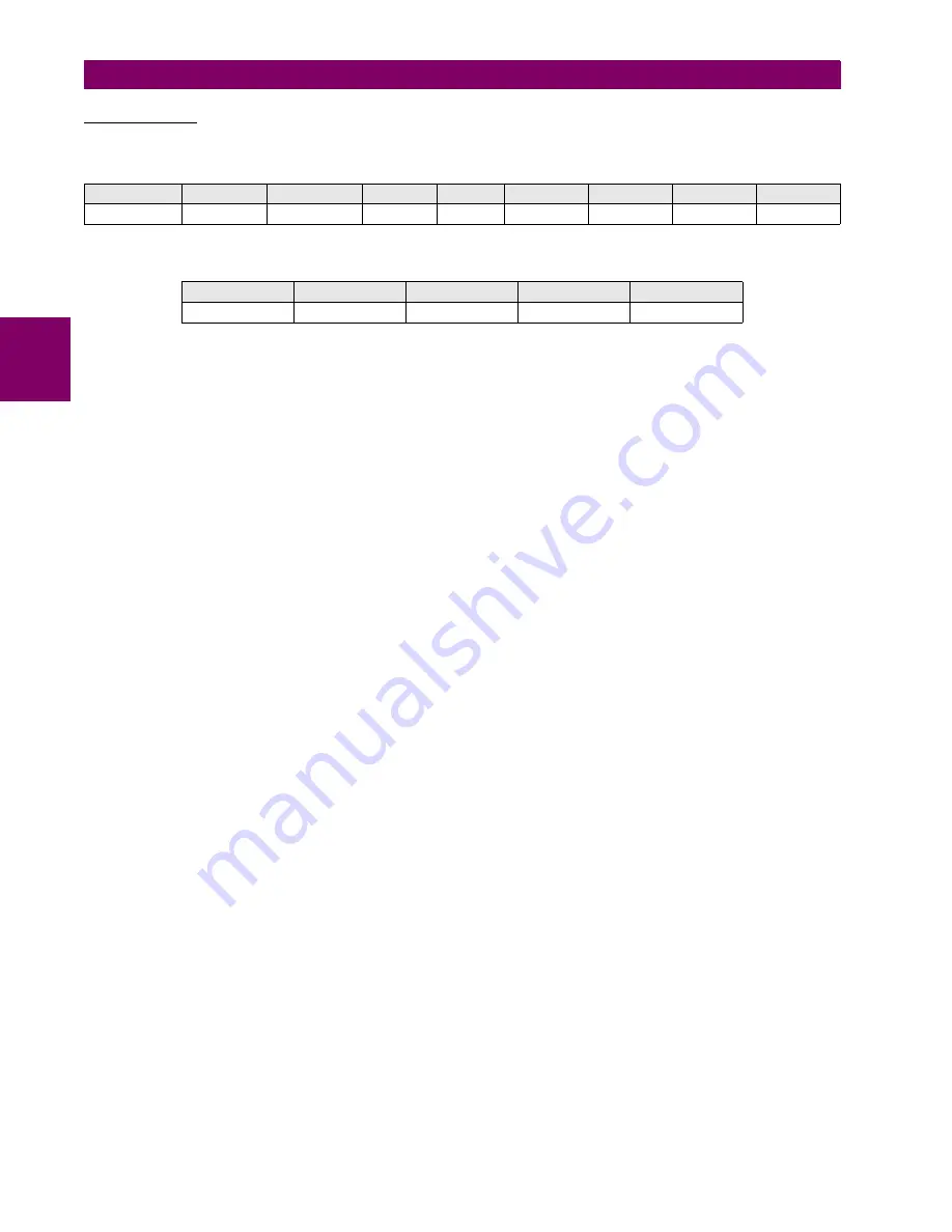
CONFIRMATION
Request
:
Reply
:
ADDRESS
FUNCTION
BEGINNING
#REGS
BYTES
#DATA0
DATA1
DATA2
CRC
01H
10H
0000H
0003H
06H
0200H
0100H
0000H
E69EH
ADDRESS
FUNCTION
BEGINNING
#REGS
CRC
01H
10H
0000H
0003H
8008H


