■
10
GE Zenith Controls
■
ZTG/ZTGD Operation and Maintenance Manual (70
R
-1000D)
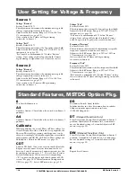
User Setting for Voltage & Frequency
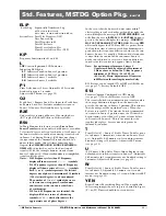
Standard Features, MSTDG Option Pkg.
Source 1
Voltage "Restore"
Factory Default: 90%
This adjustment determines the minimum acceptable
voltage required to transfer to Source 1.
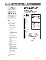
Adjust via the SET menu. Range is 85% to 100% in
1% increments (see page 18).
Once satisfied, the T timer will begin timing
to transfer to Source 1.
Voltage "Fail"
Factory Default: 80%
This adjustment determines the low voltage threshold.
Adjust via the SET menu. Range is 75% to 98% in 1%
increments (see page 18).
"Fail" must be a minimum of 2 % below "Restore"
setting. Once voltage falls below threshold, P timer
begins timing to signal Source 2 Generator to start.
Source 2
Voltage "Restore"
Factory Default: 90%
This adjustment determines the minimum acceptable
voltage required to transfer to Source 2.
Adjust via the SET menu. Range is 85% to 100% in
1% increments (see page 18).
Once satisfied, the W timer will begin timing
to transfer to Source 2.
Voltage "Fail"
Factory Default: 80%
This adjustment determines the low voltage threshold.
Adjust via the SET menu. Range is 75% to 98% in 1%
increments (see page 18).
"Fail" must be a minimum of 2 % below "Restore"
setting. Once voltage falls below threshold, T timer
will be bypassed to expedite the transfer to Source 1.
Frequency "Restore"
Factory Default: 95%
This adjustment determines the minimum acceptable
frequency required to transfer to Source 2.
Adjust via the SET menu. Range is 90% to 100% in
1% increments (see page 18).
Once satisfied, the W timer will begin timing
to transfer to Source 2.
Frequency "Fail"
Factory Default: 90%
This adjustment determines the low frequency threshold.
Adjust via the SET menu. Range is 88% to 98% in
1% increments (see page 18).
"Fail" must be a minimum of 2 % below "Restore" setting.
Once satisfied, the W timer will begin timing to transfer
to Source 2.
6
Test Switch, Momentary
A3
Auxiliary Contact: Closed when the switch is in Source 2
position.
A4
Auxiliary Contact: Closed when the switch is in Source 1
position.
Calibrate
While monitoring the actual Phase to Phase voltage lev-
els and Frequency with a calibrated test equipment, the
Phase to Phase voltage sensing and Frequency can be
adjusted accordingly. Calibration capabilities are available
for Frequency and AB, BC, CA Phase to Phase voltage for
both Sources. Adjust via SET menu (see page 18)
CDT
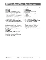
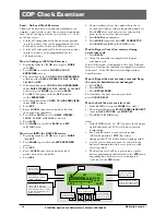
Load or NO-Load. One event exerciser with adjustable
Engine exercise timer. Exercise duration can be set
between 5 and 60 minutes in 1 minute increments. Can
be configured to run every 1, 7, 14, or 28 days. Factory
Default is 20minutes. When exerciser is impending,
(*E*) appears in the upper right hand corner of LCD
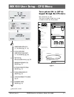
screen. See page 14-15 for instructions. Configured via
CFG (see page 17). Set via SET menu (see page 18).
DS
Disconnect Switch, Auto/Inhibit.
Inhibits transfer in either direction when in inhibit.
Allows automatic operation when in Auto.
(800-4000 Amp units)
DT
(Delayed Transition Only)
Time Delay from Neutral Switch position to Source 1
position. Adjustable 0-10 minutes in 1 second incre-
ments. Standard setting is 5 seconds Adjust via SET
menu (see page 18)
DW
(Delayed Transition Only)
Time Delay from Neutral Switch position to Source 2
position. Adjustable 0-10 minutes in 1 second incre-
ments. Standard setting is 5 seconds.Adjust via SET
menu (see page 18)
E
Engine Start Contact


