3
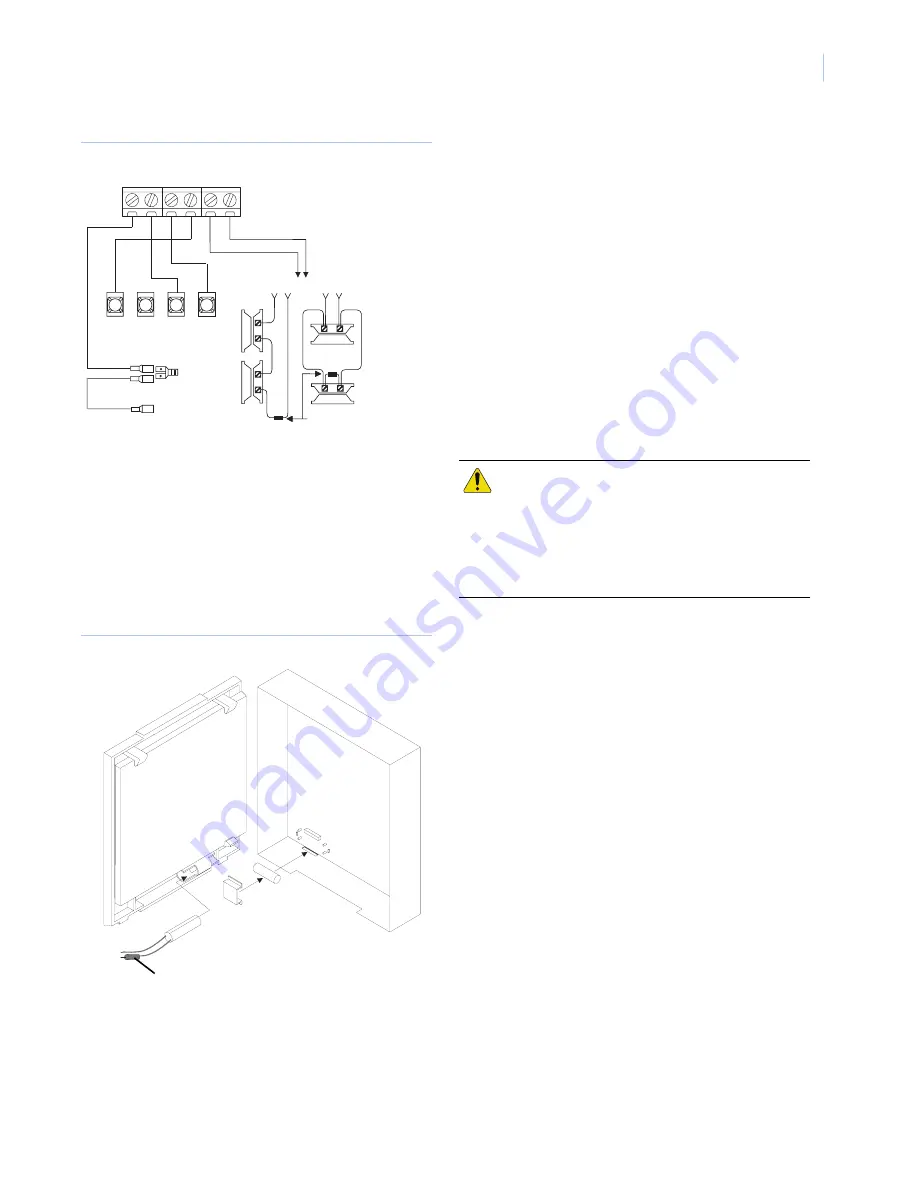
Figure 4. Basic Module Wiring for Concord 4
Installing a cover tamper switch
It is recommended that you install a cover tamper switch. Once
programmed, if someone opens the module cover, the tamper
switch opens and causes an alarm.
1.
On the module’s backplate, place the reed switch into the
reed switch holder (see
Figure 4
).
2.
Remove the magnet clip from the module cover. Next, insert
the magnet into the tabs on the module cover (see
Figure 4
).
3.
Press the magnet clip over the magnet until the clip locks
into place (see
Figure 4
).
Figure 5. Installing a Cover Tamper Switch
4.
Connect the UL listed reed switch (with 2k Ohm EOL
resistor) to a module zone or unused hardwire input.
Power up
This section describes how to power both the module and panel.
1.
Verify all wiring between the panel and module is correct.
2.
If an auxiliary supply is used, reconnect the auxiliary
supply’s backup battery and AC power. Next, reconnect the
main backup battery and restore panel AC power.
Note:
Each time a module is added or changed, you must
disconnect and reconnect panel AC power to ensure the
panel and module can successfully communicate.
Programming
1.
In the
Security
menu, enter
Installer Program
mode and set
the
Access Code Lock
feature to
OFF.
• The module’s Power LED
lights. Next, the module’s Bus
and Auto LEDs
light. The LEDs indicate successful
communication between the module and panel. The yellow
LED and bottom red LED light five to eight minutes after
entering installer program mode. Also, the sytem touchpad
displays the correct date and time.
Status LEDs
Status LEDs indicate the module’s current signal and status. The
bottom red LED indicates the module is registered and in range.
The yellow and green LEDs indicate the module’s message
status. The top LED is not used (see
Table 3
on page 4 for a
complete list of LED condition patterns).
If the Red LED remains:
•
On
– the module is registered and in range.
•
Off
– the module is out of range and not registered with the
network.
•
Flashing –
the module is registered but out of range.
If the Yellow LED remains:
•
On –
the first message has been sent to and received by
Alarm.com services.
•
Off
– a message has not been sent by the module, or a
message failed.
•
Flashing –
the first message is being sent by the module.
If the Green LED remains:
•
Off –
The module is not currently sending a message.
•
Flashing –
a message is being sent by the module.
+12V
+12V
A
A
B
B
GND
GND Z1 ZCOM
BUS
3
4
5
6
UL-Listed
normally
open (N/O)
contacts
in parallel
2.0K ohm EOL resistor
(install at last contact)
UL-Listed
normally
closed (N/C)
contacts
in series
To + terminal
on battery
To panel’s battery
+ terminal
<OR>
6 0 8 6 1 G 0 9 A . D S F
To zone
Reed switch
Magnet clip
Magnet
Module cover
Module backplate
2.0K ohm
EOL resistor
input
CAUTION:
The panel’s
Access Code Lock
feature
must be set to OFF for the system to
communicate with Alarm.com services.
The system’s date/time feature cannot
set if you press a system touchpad
button during this 5 to 8 minute period.


