


SuperBus® 2000 Wireless Gateway Module
Installation Instructions
2
Welcome Letter
tab in the
Customer Support Option
panel on the left-hand side.
If the customer does not receive the confirmation e-mail,
you may send a new confirmation e-mail by selecting
Resend Confirmation Number
in the
Customer Support
Options
panel.
Installation guidelines
• Concord (v2.6-later) panels support a maximum of one
wireless gateway
or
one automation module per system.
You cannot use both on a single panel.
• Concord 4 and Concord Express (v4) panels support one
wireless gateway and one automation module
or
two auto-
mation modules per system.
• Use four-conductor, 22- or 18-gauge stranded wire to
connect the module to a panel.
•
Do not
exceed recommended maximum wire lengths from a
panel to a module (see
Table 2
).
• Mount the module as close to the panel as possible; the
module may be mounted inside a Concord 4 or Concord
Express (v4) enclosure. The module draws a maximum of
65 mA (continuous) and up to 1600 mA (instantaneous
peaks) from the panel or auxiliary power supply.
• When powering bus devices and hardwired sensors from the
panel,
do not
exceed the panel’s total power output. Refer to
specific panel
Installation Instructions
for further detail.
Tools and supplies
• Slotted and Phillips screwdrivers
• Drill (3/8”-drive) and drill bits
• Wire cutter/stripper
• Four-conductor, 22-gauge or larger diameter stranded wire
• 2k Ohm EOL resistor (included)
• Modem antenna (included)
• #6 panhead screws and wall anchors (four each included)
Installation
Installation requires you to position and mount the module, route
and connect all wires, and install a cover tamper switch.
• Avoid locating the module in areas with excessive metal or
electrical wiring, such as a furnace or utility room.
Mounting the module
1.
Remove panel AC power and disconnect the backup battery.
2.
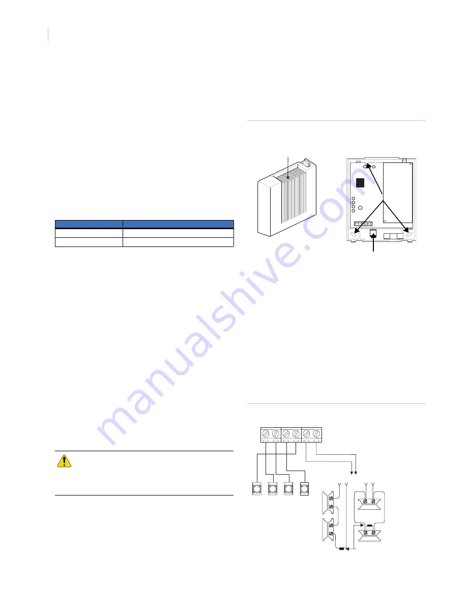
Remove the module’s enclosure cover (see
Figure 2
).
3.
Fasten the antenna to the antenna jack (see
Figure 1
on
page 1).
4.
Place the module backplate at the desired location; check for
levelness and mark the three mounting holes and the wire
access area (see
Figure 2
). Be sure to leave 12 to 18 inches
above the backplate for the antenna.
Note:
If you are mounting the module inside a Concord 4 or
Concord Express (v4) enclosure, remove the antenna
knock-out from the left expansion module and follow Steps
2 through 6 from the
SuperBus 2000 8Z Input Module’s
“Mounting the Module in a Concord Cabinet” (466-1606 Rev.
C).
Figure 2. Removing the Enclosure / Mounting Hole Locations
5.
Drill for the mounting holes and install wall anchors. Next,
secure the module’s backplate to the wall with screws.
Wiring the module
1.
Remove panel AC power and disconnect the backup battery
2.
Wire the module to panel bus and terminals (see
Figure 3
for Concord, Figure 4 for Concord 4).
3.
If desired, connect an input device to the module Z1 and
ZCOM terminals (see
Figure 3
for Concord,
Figure 4
on
page 3 for Concord 4).
Note:
Figures 3 and 4 illustrate basic module wiring connections
for Concord (v2.6-later) panels. For Concord 4 and Concord
Express (v4) panels, the module must be powered from the
battery positive (+) terminal. Refer to specific Concord 4
and Concord Express (v4)
Installation Instructions
for
further detail.
Figure 3. Basic Module Wiring Connections for Concord
Table 2.
Wire length
Gauge
Maximum Wire Length
22 ga.
40 feet
18 ga.
90 feet
CAUTION:
You must be free of static electricity
while handling electronic components.
Touch a grounded metal surface before
touching a circuit board
Press here and
remove from base
Mounting holes
Wire access
+12V
+12V
A
A
B
B
GND
GND Z1 ZCOM
BUS
3
4
5
6
<OR>
UL-Listed
normally
closed (N/C)
contacts
in series
UL-Listed
normally
open (N/O)
contacts
in parallel
2.0K ohm EOL resistor
(install at last contact)


