GE Medical Systems LOGIQ 400 Quick Start Manual Download Page 13

Quick Start 7

LOGIQ

t

 400 Quick Start Guide 

2237879–100  Rev. 0

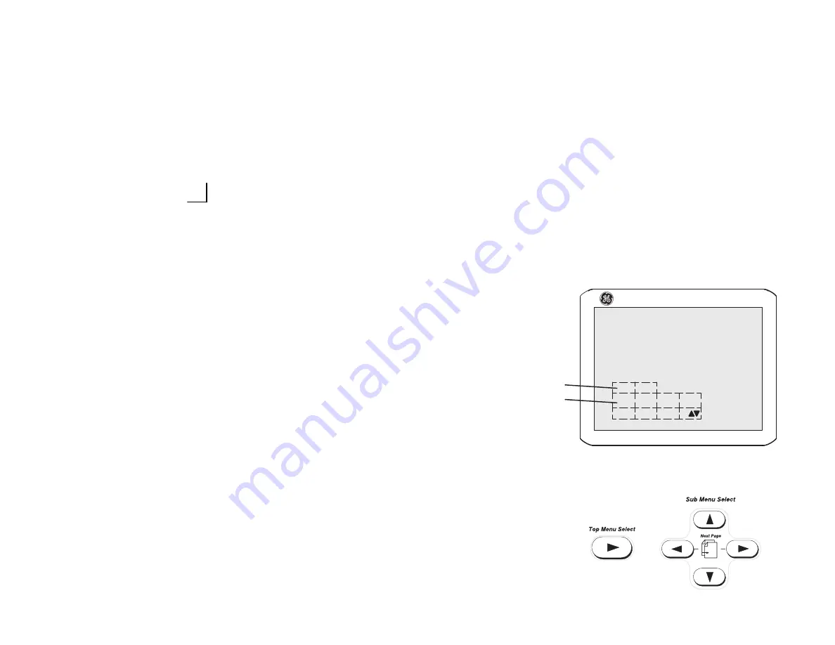
Soft Menu Control Panel

The Soft Menu Display has 8 Top Menu selections (Mode,
Preset, Set Up, ECG, Archive, DICOM, AutoSeq and Cine)
and 8 Sub Menu selections (varies depending on choice of
Top Menu selection) available.

The Top Menu Select key toggles the soft menu display
on/off or returns to the top menu display from a sub menu.

The Sub Menu Select keys turn on a sub menu, move
through the sub menu selections and pages, change sub
menu values or turn on/off sub menu selections.

The up/down arrow keys turn on the sub menu.

The left/right arrow keys move through the menu selections
and pages.

1.

Top Menu Selections

2.

Sub Menu Selections

The up/down arrow keys change the highlighted
selection value or turn the sub menu selection on/off.

}

Y

 + 

"

   or

Y

 + 

A

Next Page

   or

A

 + 

"

}

B

 + 

"

   or

Previous Page

B

 + 

A

B

LOGIQ  400 MD

1
2

1/4

Dynamic

Range

Gray

Map

Focus

Number

Focus
Positn

40

B–2

2

Summary of Contents for LOGIQ 400

Page 1: ...GE Medical Systems Training In Partnership TiP TM LOGIQ 400 Quick Start Guide 2237879 100 A Training in Partnership Program ...

Page 2: ......

Page 3: ...GE Medical Systems Technical Publications Direction 2237879 100 Revision 0 LOGIQt400 Quick Start Guide Copyright E 1999 By General Electric Co OperatingDocumentation ...

Page 4: ...MD MR3 and LOGIQ 400CL It applies to all versions of 4 01 software for the LOGIQt 400 It applies to all versions of 4 02 software for the LOGIQ 400CL GE Medical Systems GE Medical Systems Telex 3797371 P O Box 414 Milwaukee Wisconsin 53201 U S A Asia Pacific Latin America North America GE Medical Systems Ċ Europe T el 49 0 212 28 02 208 Beethovenstraße 239 Postfach 11 05 60 D 42655 Solingen GERMAN...

Page 5: ...237879 100 Rev 0 REV DATE REASON FOR CHANGE 0 April 27 1999 Initial Release LIST OF EFFECTIVE PAGES PAGE REVISION PAGE REVISION NUMBER NUMBER NUMBER NUMBER TiP Cover Page N A Title Page 0 Revision History A and B 0 Quick Start 1 thru Quick Start 40 0 ...

Page 6: ...on of this document Information pertaining to this document is maintained on GPC GE Medical Systems Global Product Configuration If you need to know the latest revision contact your distributor local GE Sales Representative or in the USA call the GE Ultrasound Clinical Answer Center at 1 800 682 5327 or 414 524 5698 ...

Page 7: ...tem safely The Quick Start Guide takes the user from system familiarization through power on patient data entry exam category preset selection scan modes adjustments basic measurements report pages recording images and power off The LOGIQt 400 manuals are written for users who are familiar with basic ultrasound principals and techniques They do not include sonography training or clinical procedure...

Page 8: ...uration while other features are options to the standard console 1 VCR Microphone 2 Probe Holder 3 MOD Drive 4 Physio Panel 5 Probe Connectors Port 2 and 3 6 Power Supply Filter 7 Air Filter 8 Probe Parking Port Port 1 9 On Off Switch 10 B W Page Printer 11 Keyboard 12 Keyboard Task Light 13 Task Light Switch optional feature or accessory LOGIQ 400 1 3 4 5 9 7 6 11 12 13 2 Î 8 10 ...

Page 9: ...v 0 Back View 1 Circuit Breaker 2 Air Filter 3 Cable Access 4 Peripheral Cable Access Door 5 Handle for Pushing 6 Monitor Arm Swivel Lock 7 Color Monitor Optional Freeze Record Foot Switch ÎÎ ÎÎ ÎÎ ÎÎ ÎÎÎ ÎÎÎ ÎÎÎ ÎÎÎ ON OFF 1 0 ON 1 2 3 4 5 6 7 Freeze Record ...

Page 10: ...ower switch is turned off S Unwrap the power cable Make sure to allow sufficient slack in the cable so that the plug is not pulled out of the wall if the system is moved slightly S Push the power plug securely into the wall outlet To power on the system ensure that the Circuit Breaker located on the back of the power supply near the bottom of the unit is turned on Press the Power On Power Off Stan...

Page 11: ...Quick Start Guide 2237879 100 Rev 0 Power On cont d During power up the screen display changes as the system runs its self diagnostics Start of diagnostic End of diagnostic Version X XX Version X XX Version X XX XXXXXXX XXXXXXX ...

Page 12: ...controls have been arranged according to function and usage This helps minimize operator movement while scanning 1 Alphanumeric Keys 2 New Patient 3 Probe Select 4 Soft Menu Controls 5 User Define 6 Mode Display and Record 7 Measurement and Annotation 8 TGC 9 Doppler and CFM Æ Ç Ø Q 1 6 7 9 5 4 3 8 2 ...

Page 13: ...u display from a sub menu The Sub Menu Select keys turn on a sub menu move through the sub menu selections and pages change sub menu values or turn on off sub menu selections The up down arrow keys turn on the sub menu The left right arrow keys move through the menu selections and pages 1 Top Menu Selections 2 Sub Menu Selections The up down arrow keys change the highlighted selection value or tur...

Page 14: ...ntinuous wave Doppler CWD probe Probe Ports All imaging probes can be plugged into either the number two or number three probe port positions Probe port position number one is inactive probe parking port It can be activated by purchasing the third probe port option NOTE Ensure that the probe port is deactivated and the image is frozen before disconnecting the probe Probe Port Position 1 Standard V...

Page 15: ...enu appears Ensure that the Blue Shift key is not active Use the Trackball to move the highlight cursor to the Exam Category Selection line Enter the desired exam number and fill in the appropriate patient data Highlight EXIT and press Return or press New Patient again when the patient entry menu data has been completed The system takes a few seconds to load new exam category parameters and calibr...

Page 16: ...xam category application preset that best describes the desired study to be performed from the factory default preset selections displayed on the monitor Select the desired probe Preset 1 2 LOGIQ 400 MD General Tech Fetal Newborn OB Diff Heart Preset 1 2 General Tech Fetal Newborn OB Diff Heart ...

Page 17: ...Doppler Color Flow Mode M Mode or Continuous Wave Doppler Mode To select CWD Mode press Blue Shift and X CWD Mode is available for sector probe only If the dual display mode split screen is desired the L and R keys activate the Left or Right displayed image Scan the desired anatomy Change modes as desired Use the mode controls to adjust the image as necessary ...

Page 18: ... Averages previous frames of image data with the current frame Imaging Freq Allows more echoes to pass through Image Softner Adjust for the amount of smoothing applied Color Allows for enabling B Mode image colorization 3D Mode Allows for 3D Mode option activation Color Tag Enables the colorization of a specific gray scale level range Tag Position Allows for the movement of the specified color tag...

Page 19: ...ge Rotate Rotates the single real time or zoomed B Mode image in 90 increments Rejectn Allows for the elimination of low level echoes from the display B Edge Enhance Brings out subtle tissue differences and boundaries by enhancing the gray scale differences corresponding to the edges of structures B 4 4 Biopsy Zone Image Rotatn Rejectn Edge Enhance SGL 0 DEG 30 MID ...

Page 20: ...ghout the image Move the slide pot to the right to increase or the left to decrease 2 Scan Area Used to assign trackball control to adjust size position B Mode sector display CFM window and horizontal size position of the real time zoom window 3 Depth To reduce depth look at a shallower image turn the Depth rotary encoder clockwise To increase depth look at a deeper image turn the Depth rotary enc...

Page 21: ...body When Reverse is active the image flips and the GE logo switches to correspond to the probe mark 6 B M Gain Controls the gain of the displayed echoes To increase decrease turn the control clockwise counterclockwise 7 Audio Volume In B B M and M Modes Acoustic Output can be adjusted with this knob 8 s Angle Controls the gain in B M and CFM B M Mode 9 Focus Position While in B Mode only Baseline...

Page 22: ...ynamic Range 3 Increase Frame Average 4 Increase Edge Enhance Improve Uniformity 1 Increase the number of focal zones 2 Decrease SCAN AREA SIZE 3 Adjust TGC to compensate for attenuation Cystic Imaging 1 Decrease the B M GAIN 2 Decrease Dynamic Range 3 Use SCAN AREA SIZE to reduce image width 4 Change Focus Number to increase number of focal zones 5 Optimize focal zone placement Technically Diffic...

Page 23: ...MTI Filter Filters out low flow velocity color Frame Average Averages color information from previous frames with the current frame Penet Penetration can be increased by lowering the operating frequency of the active probe High Resoltn Provides a quick way to maximize resolution for the CFM display Display Thrshld Gray scale level at which the overlay of color information stops Capture Displays th...

Page 24: ...tion of vessel walls Color Tag Allows for the assignment of a single color to a range of velocities Tag Positn Allows for the movement of the specified color tag range throughout the gray scale displayed ACE Reduces color artifact noise Noise Blanker Reduces the random noise generated due to the increase in Color Gain Persistence Retains the largest pixel color value until a larger value is detect...

Page 25: ...ain Adjusted overall received echo gain for CFM To increase decrease turn the control clockwise counterclockwise 2 CFM Spectrum Invert Inverts Color Flow Map assignments 3 Velocity Scale Adjusts velocity scale to accommodate faster slower blood flow velocities To increase decrease press the Velocity Scale up down arrow key 4 Baseline Shift Minimize aliasing by assigning more of the overall display...

Page 26: ...Y SCALE 3 Increase ACOUSTIC OUTPUT 4 Switch Penet on and High Resoltn on 5 Decrease W E Cancel 6 Increase Frame Average this allows gain to increase 7 Increase Packet Size 8 Reduce SCAN AREA SIZE to smallest size reasonable 9 Optimize focal zone position Improve Frame Rate Flow Dynamics 1 Decrease color window using SCAN AREA SIZE width 2 Exit COLOR FLOW to reduce B Mode image width use SCAN AREA ...

Page 27: ...caused by movement of the vessel walls S V Length Changes the size of the sample volume gate length Sweep Speed Changes the speed at which the timeline updates across the display Penet Penetration can be increased by lowering the operating frequency of the active probe Color Allows for enabling PWD or CWD Mode image colorization Color Tag Enables the colorization of a specific gray scale level ran...

Page 28: ...h part of the Doppler Trace is used for automatic measurements calculations Trace Method Choose the method used to trace the Doppler waveform in real time Peak Floor Mean or Mode There are 3 Soft Menu pages for Continuous Wave Doppler CWD imaging adjustments 3 4 Rejectn OFF Tag Positn Color Tag Sweep Speed Color OFF MID 2 4 Auto Trace Wall Filter 20 2 CWD 1 4 Dynamic Range Slant Scan 40 CWD OFF CW...

Page 29: ...pler To increase decrease turn the control clockwise counterclockwise 4 Theta Angle Correction Adjusts angle correction for flow velocity calculation To adjust the angle clockwise counterclockwise relative to the probe face turn the control clockwise counterclockwise 5 CFM Spectrum Invert Inverts Doppler spectrum assignments 6 Velocity Scale Adjusts velocity scale to accommodate faster slower bloo...

Page 30: ...equency on some applications 6 Activate B PAUSE to freeze B Mode image Scan angle is critical to Doppler sensitivity Improve Display Aesthetics 1 Activate B PAUSE to freeze B Mode image 2 Decrease GAIN 3 Increase ACOUSTIC OUTPUT 4 Use smaller sample volume size whenever possible 5 Increase decrease Dynamic Range 6 Adjust BASELINE SHIFT and VELOCITY SCALE to adjust spectral size 7 Lower Doppler Swe...

Page 31: ...level echoes from the display Edge Enhance Brings out subtle tissue differences and boundaries by enhancing the gray scale differences corresponding to the edges of structures Sweep Speed Changes the speed at which the timeline updates across the display Color Allows for enabling M Mode image colorization Color Tag Enables the colorization of a specific gray scale level range Tag Positn Allows for...

Page 32: ...n the displayed scan area The Dual Format keys work the same as in dual B Mode but both B Mode and M Mode are displayed on the left and right sides of the screen The keyboard controls that effect M Mode are as follows 1 B M Gain Controls the gain of the displayed timeline echoes To increase decrease turn the control clockwise counterclockwise 2 M D Cursor Assigns trackball control to the M Mode cu...

Page 33: ...n Freeze is activated rotate the Cine Scroll control to display individual image frames which were stored by the system NOTE Cine frame number 0 is the most current image The higher the Cine frame number the older the image The depth dynamic range and gain parameters displayed on the screen are valid for Cine frame number zero only ...

Page 34: ...e position Comments may be typed in at the non blinking cursor Pressing the Comment key assigns the trackball function to controlling the cursor The Trackball and Keyboard Arrow keys are used to move the cursor to the desired position on the image When the blinking cursor is in the desired position comments may be typed in Annotations are entered in the type over not insert mode Be careful not to ...

Page 35: ... again to exit the Blue Shift function Special Keys Language Symbols The Red Shift key enables the special symbols shown in red on the keyboard The red symbols shown in the lower right portion of a key print when the Red Shift is active and that key is pressed To print the red symbols shown in the upper right half of a key type the desired letter that uses the symbol activate Red Shift hold down t...

Page 36: ...ody Patterns A body pattern generally displayed in the lower left corner of the screen appears Cycle through the body patterns by pressing the Ellipse up or down arrow keys A Probe Orientation Marker is used to illustrate the probe position This marker can be placed with the Trackball and rotated with the Zoom Size Rotation control Press Set to complete the body pattern selection Probe Orientation...

Page 37: ...med Scan the desired anatomy and press Freeze Key Pressed MODE Key Pressed while frozen B Spectral Doppler with B M with B CFM with B Once Distance Ellipse Circle Peak Velocity Tissue Depth Distance Distance Ellipse Circle Twice Trace Circle TAMAX TAMIN TAMEAN TAMODE Time Interval Trace Circle Three Times Gray Scale Echo Level 2 Velocities Slope Time Interval Depth Difference Slope Time Interval P...

Page 38: ...LVIDd and LVPWs Press Measurement once Use the Trackball to move the cursor to the measurement start point Press Set to fix the measurement start point cursor and to display a second cursor Use the Trackball to move the second cursor to the measurement end point Press Set to complete the measurement and fix the Distance value displayed on the bottom part of the screen ...

Page 39: ...o move the cursor to either end of the major axis of the area to measure Press Set to fix the start point cursor Use the Trackball to move the second cursor to the major axis measurement end point Press the Ellipse up arrow key An ellipse having an initial circle shape appears Use the Trackball to position the ellipse as necessary and to size the measured axis Press Set to complete the ellipse mea...

Page 40: ...e activation of the measurement cursors Press the Ellipse up arrow key to increase the size of the minor axis Press the Ellipse down arrow key to decrease the size of the minor axis Press Clear once to erase the ellipse and the current data measured The original cursor is displayed to restart the measurement Pressing Clear a second time exits the measurement function without completing the measure...

Page 41: ...Zoom Size Rotation knob can be used to edit the trace line Turn it clockwise or counterclockwise to erase the line bit by bit back from its current point The erase function is limited to a small portion of the most recent trace Peak Velocity Doppler Perform a peak velocity measurement for calculations such as RI PI S D Ratio Max PG and Mean PG Press Measurement The cursor with a vertical dotted li...

Page 42: ...rsor Use the Trackball to move the second cursor to the measurement end point Press Set to complete the measurement The time interval between the two cursors is displayed Erasing Measurements Pressing Clear or unfreezing the image erases all measurements and calculations on the display Measurements and calculations however remain on the report pages Pressing New Patient erases all measurements and...

Page 43: ...nostic exam categories have report pages to summarize measurements and calculations performed while in that exam category These categories are Obstetrics Gynecology Cardiology and Vascular A report page can be displayed by pressing Measurement and selecting it from the measurement sub menu ...

Page 44: ...p Menu Select to display a sub menu of all images stored in system memory Use the Sub Menu Select left right arrow keys to highlight the desired image Press the Sub Menu Select down arrow key to display the image After recall comments measurements and body patterns can be added to the image The image is then available for printing or archival Printing Use the Record 1 or Record 2 keys to print the...

Page 45: ... different model VCR is installed on the system use the controls on the VCR Probe Cleaning Disinfection Probes should be cleaned and disinfected after each use The Probe Immersion Levels are provided with the probe but are also pictured in the Probes chapter of the User Manual NOTE Special instructions for the E721 probe are found in the Probes chapter of the User Manual F J ...

Page 46: ...onitor The message WARNING NOW START THE POWER OFF PROCESS is also displayed at the bottom of the screen While the system is running during this power down process do NOT turn off the circuit breaker in the back of the machine and do NOT unplug the system from the wall outlet If the system has not turned off five minutes after pressing the power switch off listen for hard drive activity If there i...

Reviews: