background image

0150-0193C 

33 

Calibur DVMR

e


Triplex 


About Events:

  An Event is an action that the unit acknowledges by recording at the 

Event Record Rate, yet it is not cause for an Alarm.  Events may be created two ways, 
via RS232 text insertion and Activity detection. 

Example of an Event:

  A camera is pointed at the front door inside the lobby during 

business hours.  With the Event Camera Settings Type set to Event, the unit does not 
record while the doorway is empty.  When activity motion detection senses that 
someone is entering or leaving the doorway, the unit begins recording at the Event 
Record Rate and stops recording when the motion ceases. 

RS232 Event:

  See section 7 for information about generating an Event via RS232, and 

optionally inserting ASCII text to mark the Event. 

Activity Detection Event:

 See Setup Parameters in section 3.13 for detailed 

information about configuring activity detection as an event in the menu system. 


Pre Event Duration:

  The unit will record up to 5 seconds of data ahead of the event trigger, at the 

Event Record Rate.  Select from 0 to 5 seconds. 

Post Event Duration:

  The unit will record up to 250 seconds after the completion of the Event, at the 

Event Record Rate.  Select from 0 to 250 seconds. 


Main Menu 

 Record 

 Timelapse Record Rate 

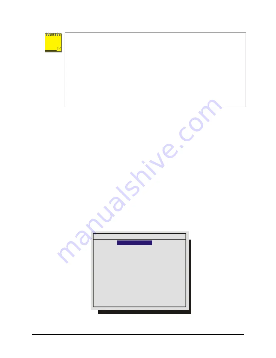
The unit records at the Timelapse Record Rate under normal conditions, when there are no alarms, 
events, or activity present.  Record rates are measured in both Pictures Per Second (pps) and Seconds 
Per Picture (spp).  

The maximum record rate per camera is inversely proportional to the number of cameras connected to 
the unit. The fewer cameras connected, the higher the maximum record rate for each camera, and vice 
versa.  The maximum record rate for multiple cameras is 48pps (NTSC)(40pps PAL).  The maximum 
record rate for a single camera is 30pps (NTSC)(25pps PAL).  

The bottom right corner of the menu contains a record duration calculator.  The top line indicates the 
estimated recording time for the unit in Time-lapse record mode only.  The bottom line indicates the 
estimated recording time, taking into consideration the amount of time the unit will spend in Activity, 
Event, and/or Alarm record mode. 


Timelapse Record Rate

Camera  1 : 

Camera  2 : 0.29 pps 3.5 spp

Camera  3 : 0.34 pps 2.9 spp

Camera  4 : 0.57 pps 1.8 spp

          :

          :

          :

Camera 15 : 0.40 pps 2.5 spp

Camera 16 : 0.40 pps 2.5 spp

0.40 pps 2.5 spp

[CANCEL]  [OK]

8 days 5 h (TL)

8 days 5 h (Total)


1.  Rotate the 

Jog 

to navigate, and the 

Shuttle 

to change the values. 

NOTE

Summary of Contents for TRIPLEX 0150-0193C

Page 1: ...C Ca al li ib bu ur r D DV VM MR Re e T Tr ri ip pl le ex x Digital Video Multiplexer Recorder User Manual...

Page 2: ...y be illegal to dispose of this battery improperly under local state or federal laws Check with your local waste management officials for disposal and recycling options CAUTION Electrostatic Sensitive...

Page 3: ...press written consent of GE Interlogix All information and specifications furnished by GE Interlogix are believed to be accurate and reliable No responsibility is assumed by GE Interlogix for neither...

Page 4: ...anel 16 2 3 Live Viewing 17 2 4 Playback 18 2 5 Recording 20 2 6 Display Options 21 2 7 Active Cameos 21 2 8 Sequencing 22 2 9 On screen Indicators 23 2 10 Triplex Mode 25 3 Menu System Overview 27 3...

Page 5: ...61 4 7 Searching For Recorded Alarms 61 5 Searching 62 5 1 Disk Analysis Screen 63 5 2 Motion Search 63 5 3 Search Filters 65 5 4 Search Results 65 6 Technical Specifications 67 7 RS232 Event Generat...

Page 6: ...es eliminate time consuming Fast Forwarding or Rewinding of tapes searching for critical data Search for recorded images or events by alarm time date motion video loss camera number and ASCII cash reg...

Page 7: ...all on screen menus Yes 3 4 4 4 Factory Defaults Installer Resets the multiplexer to the factory defaults No 4 1 1 1 Language Installer Provides access to the On screen Language menu No 1 4 1 4 Ethern...

Page 8: ...upply UPS Ventilation Ensure that the location planned for the installation of the unit is well ventilated Take note of the locations of the cooling vents in the unit s enclosure and ensure that they...

Page 9: ...Composite video output with BNC style connector 10 Y C Monitor B Output Y C video output with 4 pin mini DIN style connector 11 SCSI Port For connecting SCSI compatible archive devices 12 RS232 Port 1...

Page 10: ...the pin out specifications shown below Pin 1 Alarm Input 1 Pin 2 Alarm Input 2 Pin 3 Alarm Input 3 Pin 4 Alarm Input 4 Pin 5 Alarm Input 5 Pin 6 Alarm Input 6 Pin 7 Alarm Input 7 Pin 8 Alarm Input 8 P...

Page 11: ...Open Closes During Alarm Typical Alarm Device pin 1 Alarm Input No 16 Ground Typical wiring for Alarm 1 as Normally Open and Alarm 16 as Normally Closed Refer to each alarm device s manual for specifi...

Page 12: ...Connect the Accessory PCB supplied with the audio equipped models to the AUX port to access the Audio features Wire the audio input and output to the Accessory PCB per the pin out specifications shown...

Page 13: ...TX 6 RX 3 RX 7 Not Connected 4 Not Connected 8 Not Connected 8 2 3 4 5 6 7 1 RJ 45 socket on back panel SCSI Port Connector 50 Pin High Density SCSI 2 Gender on unit Female Compatible devices DVSe RAI...

Page 14: ...tor A then the unit will begin recording automatically Check Video Input Quality Check the picture quality by selecting each camera for full screen display If the picture quality is poor check the fol...

Page 15: ...n Menu Location Section in Manual Change the time Main Menu Time Date Set Time 3 8 Change the date Main Menu Time Date Set Date 3 8 Edit Camera Titles Main Menu Camera Setup Camera Titles Edit Titles...

Page 16: ...ugh 16 5 Reverse Play Button Playback in Reverse 6 Freeze Button Freezes camera images on screen in Live mode Pauses Playback 7 Play Forward Button Begins Playback 8 Jog Shuttle Controls Playback spee...

Page 17: ...are programmable For detailed information about programming the sequence list see section 2 8 For detailed information about configuring the dwell times in the menu system see section 3 9 Sequence But...

Page 18: ...hile in Playback mode the user may change the playback direction playback speed etc To return to Play Forward operations press the Play Forward button Play Forward Button Reverse Play To begin reverse...

Page 19: ...creen sequencing The sequence list and dwell times are programmable For detailed information about programming the sequence list see section 2 8 For detailed information about configuring the dwell ti...

Page 20: ...e indicated by the LED located directly above the Record button The unit always starts recording at the end of previously recorded data The unit will continue recording until the record button is pres...

Page 21: ...n mode on Monitor B PIP Use the Jog Shuttle to adjust the location and size of the PIP display Please note that the PIP display is only available on Monitor A in Live mode when Monitor B is in fullscr...

Page 22: ...s in the menu system see section 3 9 Autolist Custom Sequence List The Autolist feature allows the user to create a custom sequence list controlling the order the cameras are displayed and the dwell t...

Page 23: ...y Text Display Box Displays ATM POS Text data Camera Titles Camera Titles are displayed on either the upper or lower corner of the left hand side of the screen The camera title can be changed in the m...

Page 24: ...y Ejecting Play and timeleft Timeleft indicates the amount of time before the archive medium is full Only available if the unit has Background Archiving turned On Network Displays all current Network...

Page 25: ...tton is pressed the unit will enter the Triplex mode of operation When Reverse Play is pressed again the unit will revert back into the normal Playback mode While in the Triplex mode if forward play i...

Page 26: ...of the desired camera Pressing the Camera number button again displays the Status Display Box Pressing the same button a third time displays any associated ATM or cash register ASCII text Number Butt...

Page 27: ...r the Operator Password Providing limited access to the menu system Only the Operator and System View menus are available Menu Button Installer Password Providing complete menu access Use the Number b...

Page 28: ...TER button to select the highlighted menu item Exiting Menus Press the Menu button to exit a menu From the menu bar press the Menu button to exit the menu system completely Main QuickInstall Time Date...

Page 29: ...e this menu to specify if the time and date will be displayed on Monitor A Monitor B Both Monitors Not Displayed Rotate the Jog to navigate then rotate the Shuttle to change the values Save changes an...

Page 30: ...ate 1 Press the Enter button the highlighting will move to the row of numbers 2 Enter the date in Months Days Years The day of the week is calculated automatically Rotate the Jog to change the values...

Page 31: ...selection and exit the menu 2 Press the Menu button to exit the menu without making changes 3 10 Record Use this menu to Specify the record quality High Medium or Standard Specify if a camera is to b...

Page 32: ...t 1 Rotate the Jog to navigate and the Shuttle to change the values 2 To save changes and exit the menu Select OK then press the Enter button 3 Exit the menu without making changes Press the Menu butt...

Page 33: ...econds after the completion of the Event at the Event Record Rate Select from 0 to 250 seconds q Main Menu Record Timelapse Record Rate The unit records at the Timelapse Record Rate under normal condi...

Page 34: ...ttom line indicates the estimated recording time taking into consideration the amount of time the unit will spend in Time lapse Activity Event and or Alarm record mode Event Record Rate Camera 1 Camer...

Page 35: ...ach day each lasting 3 minutes on average then the of the time will be 4 1 hour 24 hours Time 4 1 Rotate the Jog to navigate and the Shuttle to change the values 2 To save changes and exit the menu Se...

Page 36: ...ding Unit overwrites all previously recorded data overwriting the oldest data first The unit does not stop recording when disk becomes full q Main Menu Record Disk Maintenance Use the Jog to select fr...

Page 37: ...Menu Alarms Alarm Latch This feature determines how the unit latches alarm conditions Selecting from the following options Latched The alarm is activated until it is silenced and acknowledged by the...

Page 38: ...respond In the example above Camera 1 will go to Preset 1 while Camera 2 will go to Preset 9 Relay Configure which relay will be triggered when an alarm is activated per camera Select from 1 2 1 2 Non...

Page 39: ...nk an alarm input to a macro If a link is created a macro will run each time that alarm is activated Alarm Select the alarm input you would like to link Macro Select the macro number you wish to link...

Page 40: ...f enabled the unit will activate Relay 1 when videoloss is detected Relay 2 If enabled the unit will activate Relay 2 when videoloss is detected Buzzer Use this setting to disable the videoloss buzzer...

Page 41: ...ld be entered as follows If the email address to be notified is john doe somecompany com then john doe should be entered in one of the Email User fields and somecompany com should be entered in the su...

Page 42: ...while archiving 3 12 Macro A macro is a recorded sequence of keystrokes The number of macros depends on the number of camera inputs 4 10 or 16 Each macro can have up to 32 keystrokes Use this menu to...

Page 43: ...Reset Relay 1 output Function then 3 Pause macro for 1 second Function then 4 Pause macro for 5 seconds Function then 5 Activate Relay 2 output Function then 6 Reset Relay 2 output Function Function...

Page 44: ...Function button followed by the Number button of the desired macro While running the macro is indicated on screen as the letter F and the macro number The user can cancel the macro at any time by pre...

Page 45: ...f the Motion Detection you wish to configure Motion Detection Parameters Setup CANCEL OK Camera Motion Detection Type Sensitivity Relay Output Link to Event Rejection Target Size Link to Alarm 01 ACTI...

Page 46: ...ously triggered zones and the persistence of motion in a scene The Low setting is the most sensitive to motion The Medium setting will filter out most false alarm situations due to sudden luminance ch...

Page 47: ...ensitivity Raise and lower the red bar to change the motion detection sensitivity Use the Play Forward button to increase the sensitivity level and the Play Reverse button to decrease the sensitivity...

Page 48: ...o navigate the cursor in the camera title 4 Rotate the Jog to navigate the cursor in the character bank 5 Press the Number 1 button to insert a blank character or press the Number 2 button to insert t...

Page 49: ...to change the values Auto Disable Now This feature detects which inputs have video signals and which are experiencing videoloss When this feature is activated the unit will automatically disable the...

Page 50: ...uminance Histogram Black 0 L White Luminance 3 15 Archive Setup Data recorded by the unit can be archive to an external archive device Use this menu to Turn Background Archiving mode Off and On Erase...

Page 51: ...dress for the RS485 network Configure the Ethernet address and networks settings q Main Menu Communications RS232 Select the Port you wish to configure and press the ENTER button Port 1 Use this menu...

Page 52: ...to the Modem Init String and advance to the next character 6 Use the Number 1 button to insert a blank character 7 When finished press the Enter button 8 To save the changes and reboot select OK then...

Page 53: ...his menu Highlight the item you wish to select Save changes and exit the menu Press the Enter button Exit the menu without making changes Press the Menu button 3 19 Factory Settings Return To Factory...

Page 54: ...rnet Password 1 Enter the new password using the Number buttons 2 Highlight OK then press the Enter button 3 Re enter the password 4 Highlight OK then press the Enter button The user will be prompted...

Page 55: ...ed number of menu items These menu items are primarily monitor display setup options so that the user may personalize the monitor displays during their shifts Other options include video archive setup...

Page 56: ...Input Enable Disable 1 Enabled 0 Disabled Normally Open or Normally Closed 0 Open C Closed Macro Macro number if activated Alarm Action Freeze 1 Freeze 0 No Freeze Cameras Primary camera in alarm and...

Page 57: ...d Rate In pictures per second pps Pre Event Duration 0 to 5 seconds Post Event Duration 0 to 200 seconds Acitvity Record Rate In pictures per second pps Record Quality High Medium or Low View Screen 5...

Page 58: ...arm Record Mode Interleaved Exclusive or No Change Full Screen Alarm Yes or No This feature is not available on the 4 Channel units Global Alarm Record Rate In pictures per second pps Pre Alarm Durati...

Page 59: ...cameras when an alarm is detected Record Rate Record Rate can be increased by recording at the Alarm Record Rate see section 3 10 and by Interleaved or Exclusive Recording see Alarm Record mode in se...

Page 60: ...t switches to a sequenced display of all cameras in alarm 4 Channel Units Single Alarm Unit switches to a full screen display of the camera in alarm Additional Alarms Unit switches to a sequenced disp...

Page 61: ...rm is indicated on screen by a flashing red A in its cameo Alarm LED lights to indicate an alarm condition There is no change in the playback or Triplex multiscreen based on playback of recorded alarm...

Page 62: ...10 0 00 00 38 003 01 21 2002 20 10 10 0 01 07 22 004 01 22 2002 20 07 10 0 00 00 07 005 01 23 2002 20 07 10 0 00 08 56 006 01 24 2002 20 07 10 0 00 00 06 007 01 25 2002 20 07 10 0 05 57 31 008 01 26...

Page 63: ...s the cursors move across the screen the corresponding disk time is indicated in the upper right of the screen The video representations are color coded by category Rotating the Shuttle expands Zooms...

Page 64: ...disable motion detection on the screen within blocks that form a 16 x 16 grid Pressing the Function key while in this screen overlays a help screen with all the available commands MENU Exit Activity...

Page 65: ...m Disk 2 Play from Archive 3 Copy from Disk to Archive 4 Copy from Archive to Disk Hit Camera buttons to select deselect individual cameras Use the Zoom button to globally select deselect cameras to s...

Page 66: ...down ENTER to play event SEQ to repeatedly play event 9 matches found Some options may be unavailable depending on the type of search performed These options are not displayed When archiving the unit...

Page 67: ...RJ 45 Connector Camera Inputs BNC connectors Auto Terminating Color Mono Monitor A Output Y C 4 pin Mini DIN Connector Monitor B Output Y C 4 pin Mini DIN Connector Monitor A Output Composite BNC Conn...

Page 68: ...elay Outputs On screen Indicators Status Retrievable via RS232 port Motion Detection Zones Per Camera 256 16 x 16 grid Sensitivity Settings 10 levels Gray Levels Per Zone 256 levels Motion Detection S...

Page 69: ...Camera byte indicates the camera associated with the text The valid range is from 0 to 15 Event byte usage is described in the following section String field contains text characters The string can b...

Page 70: ...start and end bits are set the associated text will be stored with the next recorded field for that camera The post event timer will be started after which the selected camera will resume recording a...

Page 71: ...9 Camera 12 20 Camera 13 21 Camera 14 22 Camera 15 23 Camera 16 24 Reserved 25 40 Menu 41 Enter 42 Reserved 43 Macro 44 Reserved 45 49 Monitor B 50 Reserved 51 63 Left Arrow 64 Right Arrow 65 Up Arrow...

Page 72: ...block 255 must be set to 0 iii Requesting data from the DVMRe When a message of type 0xBB is sent to the DVMRe Triplex it will respond by sending 16 bytes of requested data a Read Alarm History List B...

Page 73: ...is page and use it to keep a record of the programmed macro functions 9 1 Macro Functions Table Macro Number Description 1 2 3 4 5 6 7 8 9 10 11 12 13 14 15 16 Function Sequence Daylight Savings Time...

Page 74: ...0150 0193C 74 Calibur DVMRe Triplex 9 2 Scheduled Macro Table Event Day Time Macro to Run 1 2 3 4 5 6 7 8 9 10 11 12 13 14 15 16 17 18 19 20...

Page 75: ...ial Authorization number RMA The unit s serial number must be provided before a RMA number can be issued Units returned to the factory for service must have freight and insurance prepaid and must show...

Page 76: ...all non warranty repairs the customer will be billed for parts labor and shipping Labor will be billed in half hour increments Note Customers requesting an estimate prior to repair will be notified by...

Page 77: ...0150 0193C...

Reviews: