


GDS-68XP Operation & Maintenance Manual, Revision 3.5
Page 18
MODBUS
system
architecture
requires
that
the
devices
in
any
MODBUS
loop
be
connected
in
a
daisy
‐
chain
layout.
This
minimizes
signal
reflections
and
improves
signal
noise
margin.
A
MODBUS
Termination
Jumper
installs
a
load
resistor
across
the
MODBUS
signal
lines
and
should
only
be
set
to
“A”
(ON)
at
the
last
device
in
the
string
(See
Fig.
5
‐
3).
Cable
selection
for
MODBUS
systems
is
important
for
both
signal
integrity
and
power
distribution.
MODBUS
/
RS
‐
485
transmissions
use
low
‐
voltage
differential
signaling
to
achieve
reasonable
data
rates
over
very
long
distances,
up
to
4000
feet
without
a
repeater.
For
MODBUS
data
signals,
GDS
Corp
recommends
20GA
to
24GA
twisted
shielded
cable.
Daisy
‐
chain
power
distribution
may
require
larger
gauge
wire
since
it
is
critical
that
the
supply
voltage
for
the
GDS
‐
68XP
at
the
far
end
of
the
string
not
fall
below
22VDC
during
power
‐
up.
Note
that
while
the
GDS
‐
68XP
has
two
sets
of
wiring
terminals
for
MODBUS
“A”
and
“B”
signals,
daisy
‐
chain
power
wiring
requires
that
two
wires
be
installed
in
the
“+24”
and
“GND”
terminals
on
the
GDS
‐
68XP
I/O
Power
Supply
board.
This
can
be
difficult
if
wire
sizes
are
larger
than
#18GA.
For
these
reasons,
if
MODBUS
is
required
GDS
Corp
recommends
the
addition
of
the
MODBUS
Wiring
Junction
Box
(see
Fig.
5
‐
7).
This
option
minimizes
the
need
to
access
wiring
inside
the
GDS
‐
68XP,
provides
individual
wire
landing
points
for
incoming
and
outgoing
MODBUS
and
power
wiring
and
shields,
and
makes
it
easy
to
temporarily
disconnect
the
GDS
‐
68XP
power
or
MODBUS
connections
without
affecting
any
other
MODBUS
device.
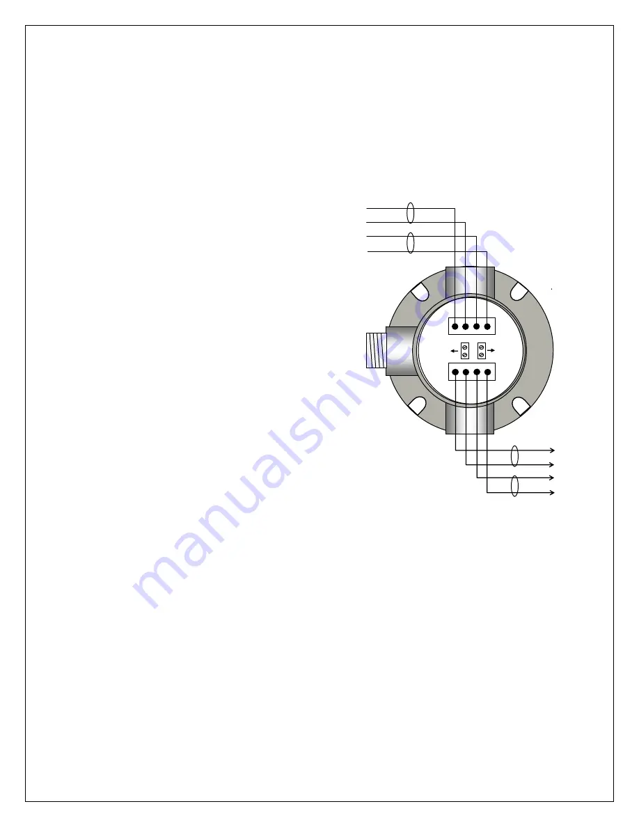
+24
GND
A
+24
GND
A
PW
R
to
MO
D
B
U
S
to
+24
GND
“A”
“B”
+24
GND
“A”
“B”
Figure 5-4: MODBUS Wiring
Junction Box