


GDS-68XP Operation & Maintenance Manual, Revision 3.5
Page 17
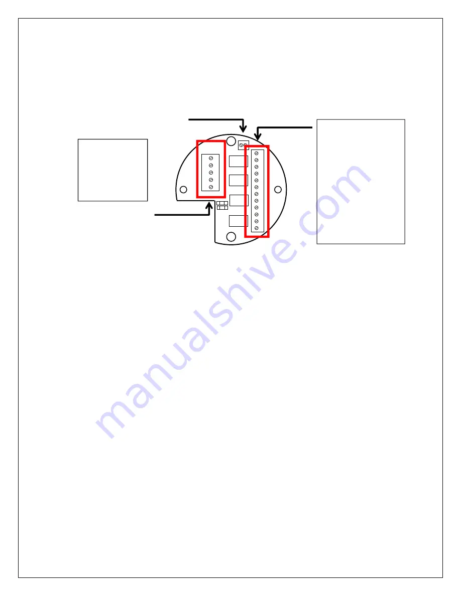
RELAY
CONNECTIONS
(OPTIONAL)
The
optional
GASMAX
CX
Relay
/
dual
MODBUS
RTU
slave
interface
is
connected
“piggyback”
to
the
back
of
the
GASMAX
CX
Display
Assembly
and
supplies
three
level
alarm
relays,
a
FAULT
relay
and
dual
RS
‐
485
Modbus
RTU
serial
ports.
Figure 5-3: RELAY / MODBUS Connections
Relays
K1,
K2
and
K3
provide
a
contact
closure
if
the
Alarm
1
(“K1”)
or
Alarm
2
(“K2”)
or
Alarm
3
(“K3”)
limits
are
exceeded.
Alarms
can
be
programmed
to
trigger
above
or
below
a
certain
value,
work
as
normal
or
‘failsafe’
and
can
be
made
to
latch
if
desired.
Relay
K3
indicates
a
FAULT
condition
in
the
sensor,
microprocessor
or
flow
system.
Remote
Alarm
Reset
can
be
used
to
acknowledge
an
Alarm
2
relay
contact
closure.
Wiring
from
any
remote
pushbutton
to
TB3
should
be
shielded
and
protected
from
noise
spikes
to
prevent
false
Alarm
Reset
commands.
WARNING:
RELAY
CONTACTS
ARE
RATED
FOR
RESISTIVE
LOADS
ONLY!
INDUCTIVE
LOADS
MAY
CAUSE
ARCING
WHICH
SHORTENS
LIFE
AND
MAY
INTERFERE
WITH
SENSOR
DATA.
MODBUS
CONNECTIONS
(OPTIONAL)
The
dual
optional
GDS
‐
68XP
MODBUS
RTU
interface
allows
remote
controllers
or
PLCs
to
monitor
most
aspects
of
operation,
including
real
‐
time
data,
range
and
alarm
setpoints
and
alarm
and
fault
status
bits.
The
GDS
‐
68XP
interface
supports
9600
Baud
RS
‐
485
differential
signaling
only.
Access
to
each
MODBUS
RS
‐
485
interface
is
via
TB2
on
the
optional
Relay
/
MODBUS
board
mounted
on
the
back
of
the
GASMAX
CX
display
module
(See
Fig.
5
‐
3).
Separate
input
and
output
terminals
for
MODBUS
“A”
and
“B”
signals
are
available.
A
center
terminal
to
tie
incoming
and
outgoing
shield
connections
is
also
provided.
2
3
4
1
TB1
5
B
S
A
A
B
TB2
Relay
Wiring:
1
Fault
1
NC
2
Fault
1
Common
3
Fault
1
NO
4
Relay
3
NC
5
Relay
3
Common
6
Relay
3
NO
7
Relay
2
NC
8
Relay
2
Common
9
Relay
2
NO
10
Relay
1
NC
11
Relay
1
Common
12
Relay
1
NO
MODBUS
interface
Remote
Alarm
Acknowledge
Modbus
Wiring:
1
Modbus
A
2
Modbus
B
3
Shield
Tie
Point
4
Modbus
A
5
Modbus
B