GASMAX CX + GDS-IR Operation & Maintenance Manual, Revision 1.0
Page 26
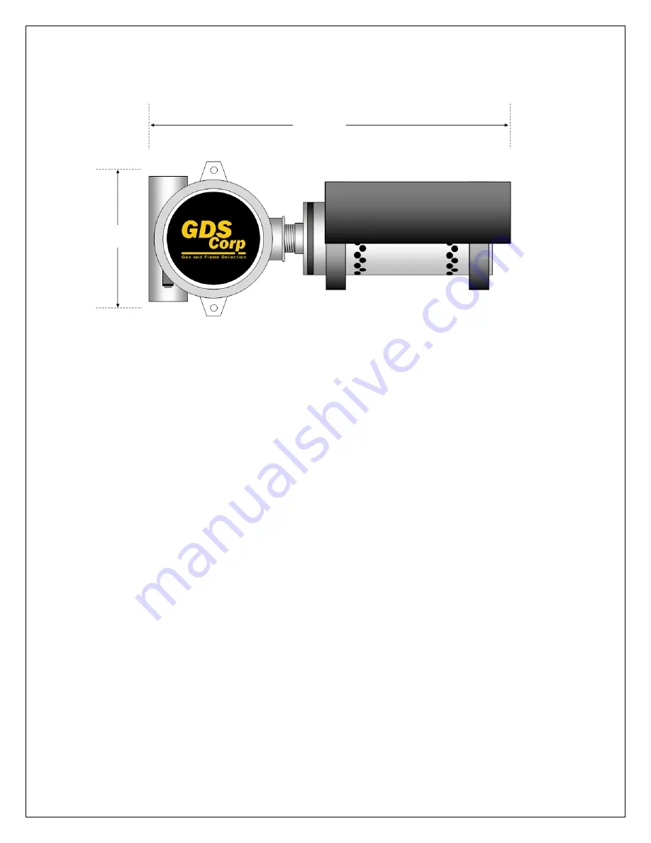
Figure 10-2 GASMAX CX + GDS-IR DIMENSIONS (Horizontal)
5.0”
12.25”
Page 1: ... Butler Road League City TX 77573 409 927 2980 409 927 4180 Fax ww gdscorp com Operation and Maintenance Manual GASMAX CX GDS IR GASMAX CX Gas Monitor with GDS IR Infrared Sensor for Combustibles and Carbon Dioxide ...
Page 2: ...TION MANUAL COMPLETELY BEFORE OPERATING OR SERVICING ATTENTION POUR DES RAISONS DE SÉCURITÉ CET ÉQUIPEMENT DOIT ÊTRE UTILISÉ ENTRETENU ET RÉPARÉ UNIQUEMENT PAR UN PERSONNEL QUALIFIÉ ÉTUDIER LE MANUE D INSTRUCTIONS EN ENTIER AVANT D UTILISER D ENTRETENIR OU DE RÉPARER L ÉQUIPEMENT REVISION HISTORY Revision 1 0 2 15 17 Initial Release Copyright 2017 GDS Corp All Rights Reserved P N 1200 0934 01 ...
Page 3: ...ITIAL STARTUP ___________________________________________________ 12 5 CALIBRATION ______________________________________________________ 16 6 MAINTENANCE_____________________________________________________ 19 7 TROUBLESHOOTING_________________________________________________ 21 8 SPECIFICATIONS ____________________________________________________ 23 9 SPARE PARTS ________________________________...
Page 4: ... 3 6 MODBUS WIRING JUNCTION BOX 11 FIGURE 3 7 MODBUS JBOX LOCATION OPTIONS 11 FIGURE 4 1 GASMAX SINGLE CHANNEL DISPLAY 12 FIGURE 4 2 GASMAX DUAL CHANNEL DISPLAY 12 FIGURE 4 3 USER MENU SCREEN 13 FIGURE 4 4 ACCESSING CAL MODE 13 FIGURE 4 5 GASMAX DATA DISPLAY 14 FIGURE 4 6 GASMAX TREND DISPLAY 14 FIGURE 5 1 CALIBRATION FLOWCHART 16 FIGURE 5 2 CALIBRATION SETUP 17 FIGURE 5 3 IR ZERO FOR LOCAL SENSOR...
Page 5: ...ain gases in ambient air Accuracy in atmospheres containing steam or inert gases cannot be guaranteed The GDS IR infrared sensor may be mounted vertically or horizontally Do not mount the GDS IR upside down If using the GDS Rain Shield IRRS the sensor must be mounted horizontally Do not paint transmitter or sensor assembly Do not operate the GASMAX CX GDS IR if the enclosure is damaged or cracked ...
Page 6: ...X GDS IR Local Sensor Figure 2 2 GASMAX CX GDS IR Remote Sensor The GASMAX CX is enclosed in a CSA FM IECEx certified anodized aluminum explosion proof yellow enclosure designed to protect the electronics and make it easy for workers to identify in industrial environments The screw on front cover is easily removed for installation and maintenance however built in user interface magnetic switches a...
Page 7: ...ss 1 Division 1 hazardous areas Installation in these areas should follow best industry standard practices and all appropriate electrical codes Generally these codes require rigid metal conduit poured seals and other installation elements necessary to ensure safety For maximum protection against RF interference or electrical surge the GASMAX CX enclosure all remote sensors and interconnecting cond...
Page 8: ...er cable CONNECTING TO AN ETHERNET NETWORK The GASMAX CX provides a standard 10 100 Ethernet network interface on the Power I O board as shownin Fig 4 2 Both DHCP and fixed IP address modes are provided The Ethernet interface provides access to the MODBUS database via MODBUS TCP as well as remote access and setup via a built in web server COM 420 OUT 2 420 OUT 1 PWR R PWR C 420 IN 1 A COM 420 IN 2...
Page 9: ...CX Optional Relay MODBUS Interface NOTE THE FAULT RELAY IS PROGRAMMED TO OPERATE IN FAILSAFE MODE ONLY THE RELAY IS ACTIVE WHEN NO FAULT EXISTS C NO AND BECOMES INACTIVE IF A FAULT IS PRESENT C NC COM 420 OUT 2 420 OUT 1 PWR R PWR C 420 IN 1 A COM 420 IN 2 CH 1 CH 2 E NET LOCAL SENSOR TO DISPLAY 2 3 4 1 TB1 5 B S A A B TB2 Relay Wiring 1 Fault 1 NC 2 Fault 1 Common 3 Fault 1 NO 4 Relay 3 NC 5 Rela...
Page 10: ...he GASMAX CX and a remote GDS IR sensor is provided by the customer The interface requires a four conductor shielded cable as shown below The remote junction box provides both a magnetic switch and local pushbutton for the IR Zero function Figure 3 5 GASMAX CX GDS IR Remote Sensor Wiring Diagram COM 420 OUT 2 420 OUT 1 PWR R PWR C 420 IN 1 A COM 420 IN 2 CH 1 CH 2 E NET LOCAL SENSOR TO DISPLAY Bla...
Page 11: ...that the supply voltage for the GASMAX CX at the far end of the string not fall below 12VDC during power up Note that while the GASMAX CX has two sets of wiring terminals for MODBUS A and B signals daisy chain power wiring requires that two wires be installed in the 24 and GND terminals on the GASMAX CX I O Power Supply board This can be difficult if wire sizes are larger than 18GA For these reaso...
Page 12: ... INTERFACE The GASMAX CX display is shown in Figure 5 1 There are four magnetic switches on the face of the GASMAX CX arranged in a quadrant around the LCD display these are labeled NEXT EDIT DOWN CAL and UP To activate or press a magnetic switch swipe the magnetic wand near the switch For the balance of this manual the term press will be used to describe activation of any key via the magnetic wan...
Page 13: ...AY COMPROMISE THE SAFETY OF THE GAS DETECTION SYSTEM BE SURE TO UNDERSTAND WHAT TO CHANGE AND WHY BEFORE ENTERING THE USER MENU Press the DN CAL key followed by the EDIT key to access CALIBRATION MODE Regular calibration is critically important to the continued safe operation of any gas detection system See Chapter 6 for more information on calibration Figure 4 4 Accessing Cal Mode NOTE TAKE CARE ...
Page 14: ...ation if LED is ON the relay will be de energized In dual channel mode if either channel is in alarm the corresponding A1 or A2 indicator LED and relay will be energized Figure 4 5 GASMAX Data Display Two LEDs monitor the MODBUS RS 485 transmit TXD and receive RXD buffers Flashing indicates sent or received data RXD will flash whenever a message from the MODBUS master is received and TXD will flas...
Page 15: ...IONAL ALARM RELAYS ARE NOT INSTALLED ALARM SETTINGS AFFECT THE OPERATION OF THE FRONT PANEL DISPLAY ONLY SEPARATE ALARM SETTINGS MAY NEED TO BE PROGRAMMED IN THE 4 20MA RECEIVING DEVICE ALARM OPERATION FAULT FAULT is typically used to indicate FAULT conditions that suggest sensor failure or out of measurement range conditions SYSTEM SETUP Once operational the user should verify the following setti...
Page 16: ...tion gas that has passed its expiration date Check the SPAN GAS VALUE setting and make sure it matches the calibration gas value Always use a GDS Corp calibration cup or wrap that completely surrounds the sensor head Be sure to use ZERO AIR a mixture of 21 oxygen and 79 nitrogen as a zero reference unless you are certain that no target gas exists in the area Ambient gas may result in an elevated z...
Page 17: ... 2 Calibration Setup STEP ONE GDS IR ZERO 1 Connect the cylinder of zero air to the fixed flow regulator and connect the tubing to the calibration port on the bottom of the GDS IR sensor 2 Install the GDS IR calibration wrap accessory around the GDS IR to block the sensor s gas access holes 3 Turn on the regulator and allow gas to run for 30 seconds 4 Local sensor Use the magnetic wand to trigger ...
Page 18: ... Double check the concentration and expiration date The reading will increase as the span gas flows into the sensor 5 After the reading is stable approximately 1 minute press the EDIT key to complete the SPAN GAS calibration If the SPAN calibration is successful the display flashes REMOVE CAL GAS and starts the CAL PURGE delay 6 Immediately shut off the regulator and remove the calibration wrap At...
Page 19: ...ds to the type of fault detected The GDS IR should be checked regularly for damage water ingress or hydrophobic filter clogging due to excessive dust or dirt If the hydrophobic filter has become contaminated by dust dirt or moisture unscrew the sensor head cover remove the set screw and gently slide the filter down to remove See Fig 7 1 Carefully clean the filter with compressed air and reinstall ...
Page 20: ...n This will eventually allow the waveguide assembly to be removed from the GDS IR 5 Using a cotton swab and alcohol clean the surfaces of the Receiver and Source as shown 6 Reassemble the GDS IR 7 Perform a hardware zero once the sensor is completely reassembled NOTE IT IS NOT NECESSARY TO REMOVE POWER FROM THE GDS IR TO PERFORM THIS CLEANING PROCESS Figure 6 1 GDS IR Disassembly ...
Page 21: ...MAX count settings are correct MIN counts should be 800 which corresponds to 4mA and MAX counts should be 4000 which corresponds to 20 mA Verify that the GASMAX MODBUS address matches the address programmed into the controller s channel configuration CONTROLLER SHOWING MODBUS COMM ERROR Check for incorrect MODBUS polarity swap A and B if unsure no damage will occur Verify that MODBUS master is req...
Page 22: ... Note that a COLD BOOT will reset certain values to their default setting including the MODBUS address value If a Smart Sensor is connected to a local sensor head the GASMAX will reload the sensor type range cal span value and other sensor related values automatically ...
Page 23: ...ndard Output Three wire 4 20mA current source outputs with fault and overrange indication Maximum loop resistance is 750 ohms with standard 24VDC supply Optional Output Relay MODBUS interface with 4x 5A SPDT programmable alarm relays Temperature Electronics 40 C to 60 C Memory On board non volatile memory retains all user settings Housing Aluminum housing with epoxy paint standard 316 stainless st...
Page 24: ...are Parts Yellow Enclosure 10 0160 GASMAX Enclosure Electronics Nest Assembly 10 0387 Display Board 10 0388 Relay MODBUS Board 10 0390 Power I O Board 20 0195 GDS IR Sensor Personality Board GDS IR Sensor GDS IR Part number determined by target gas type Contact Factory for details 20 0236 Rain Shield 20 0243 Calibration Wrap ...
Page 25: ...GASMAX CX GDS IR Operation Maintenance Manual Revision 1 0 Page 25 10 DRAWINGS AND DIMENSIONS Figure 10 1 GASMAX CX GDS IR DIMENSIONS Vertical 5 0 5 25 12 25 ...
Page 26: ...GASMAX CX GDS IR Operation Maintenance Manual Revision 1 0 Page 26 Figure 10 2 GASMAX CX GDS IR DIMENSIONS Horizontal 5 0 12 25 ...
Page 27: ......
Page 28: ...GDS Corp 1245 Butler Road League City TX 77573 409 927 2980 409 927 4180 Fax ww gdscorp com ...