


GASMAX CX + GDS-IR Operation & Maintenance Manual, Revision 1.0
Page 19
6
MAINTENANCE
GASMAX
CX
Normal
maintenance
for
the
GASMAX
CX
primarily
involves
periodic
calibration
on
standard
intervals.
GDS
Corp
recommends
calibration
at
least
every
three
months,
or
more
often
if
temperature
extremes,
vibration,
the
presence
of
incompatible
gases
or
other
environmental
factors
may
accelerate
the
deterioration
of
the
sensor
element.
Calibration
should
also
include
inspections
for
clogged
or
wet
sensor
heads,
cracked
or
damaged
enclosures
and
water
incursion
inside
conduit
or
junction
boxes.
GDS
‐
IR
INFRARED
SENSOR
When
power
is
applied
to
the
GDS
‐
IR,
it
enters
a
one
‐
minute
warm
‐
up
period.
The
output
current
will
be
0.8
mA
during
the
warm
up
time
period.
At
the
end
of
the
warm
‐
up
period
with
no
faults
present,
the
GDS
‐
IR
automatically
enters
normal
operating
mode
and
outputs
4.0
mA.
If
a
fault
is
present
after
warm
‐
up,
the
detector
current
output
will
indicate
a
fault.
In
the
normal
operating
mode,
the
4
‐
20
mA
signal
level
corresponds
to
the
detected
gas
concentration.
In
the
event
of
an
overrange
gas
release,
the
GDS
‐
IR
will
indicate
an
overrange
condition
up
to
approximately
23mA.
Excessive
gas
will
not
harm
the
sensor
and
the
output
will
return
to
normal
once
the
gas
dissipates.
In
the
event
that
the
internal
microprocessor
detects
a
fault
condition,
the
output
will
be
set
to
a
specific
mA
reading
that
corresponds
to
the
type
of
fault
detected.
The
GDS
‐
IR
should
be
checked
regularly
for
damage,
water
ingress
or
hydrophobic
filter
clogging
due
to
excessive
dust
or
dirt.
If
the
hydrophobic
filter
has
become
contaminated
by
dust,
dirt
or
moisture,
unscrew
the
sensor
head
cover,
remove
the
set
screw
and
gently
slide
the
filter
down
to
remove
(See
Fig.
7
‐
1).
Carefully
clean
the
filter
with
compressed
air
and
reinstall.
The
GDS
‐
IR
can
operate
without
the
hydrophobic
filter
installed
if
the
atmosphere
contains
little
dust
or
moisture.
There
are
no
user
‐
serviceable
components.
CLEANING
THE
GDS
‐
IR
OPTICS
If
necessary,
the
GDS
‐
IR
can
be
partially
disassembled
to
allow
cleaning
of
the
optical
windows
covering
the
IR
source
and
IR
receiver.
To
disassemble
the
GDS
‐
IR,
perform
the
following
steps
(See
below):
1.
Unscrew
the
outer
cover
in
a
counter
‐
clockwise
direction
(looking
up
from
underneath)
2.
Locate
the
small
set
screw
that
holds
the
hydrophobic
filter
in
place.
Carefully
remove
the
screw
using
a
flat
‐
blade
screwdriver.
3.
Gently
slide
the
hydrophobic
filter
down
and
set
aside.
4.
Place
one
Allen
wrench
in
the
hole
marked
“A”
to
hold
the
top
section
of
the
optical
waveguide
in
place.
Place
another
through
the
hole
marked
“B”
in
the
lower
section
of
the
optical
waveguide.
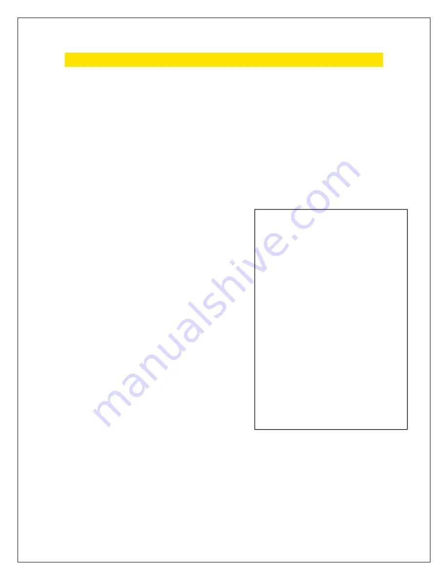
Sensor
Output:
0.0 mA
Unit Fault
0.2 mA
Reference channel fault
0.4 mA
Analytical channel fault
0.8 mA
Unit warm up
1.0 mA
Optics fault
1.2 mA
Zero drift fault
1.6 mA
Calibration fault
2.0 mA
Unit spanning
2.2 mA
Unit zeroing
4.0 mA
Zero gas level (0%LEL)
5.6 mA
(10%LEL)
8.0 mA
(25%LEL)
12 mA
(50%LEL)
16 mA
(75%LEL)
20 mA
Full scale (100% LEL)
20.1- 23 mA Over-range (> 100% LEL)


