


SM336 Manual
3
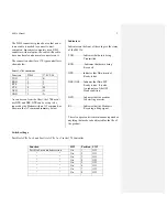
The DB-9 connector is pinned out so that a one-
to-one cable is needed to connect to most
computers. Since most computers use a DB-9
connector with male pins, the cable will need to
have one female and one male connector on it.
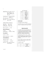
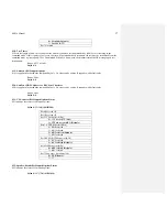
The connection chart for a 170 type controller is
shown below:
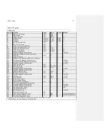
Table 3, 170 Connections
Function DB-9
170
C2,20
TXD 3
K
RXD 2
L
RTS 7
J
CTS 8
M
DCD 1
H
GND 5
N
As can be seen from the Chart, the 170 doesn’t
use DTR and DSR. DTR can be set up to be
ignored by the Modem with an AT command, as
shown in the AT command summary below.
Indicators
Indicators on the front of the card give the status
of the SM336.
TXD…………Indicates that data is being
Transmitted
RXD………….Indicates that data is being
Received
DTR……….. Indicates that Data terminal
Ready is true.
DSR (OH)…..Indicates that Data SET
Ready is true. It is also
An indicator of the OFF
Hook
condition.
DCD…………Indicates that the modem
Is detecting a carrier.
RI……………Indicates that the Modem is
Receiving a Ring signal.
There is no preventative maintenance required or
anything that needs to be adjusted for the life of
the product.
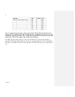
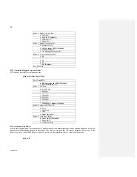
Switch settings:
Port B is ACIA 2 or 4 and Port A is ACIA 1 or 3 in the 170 Controller.
Function SW2
Position SW3
Port B to Smart modem section
On
1
Off
“
“ On 2 Off
“
“ On 3 Off
“
“ On 4 Off
“
“ On
5
Off
“
“ On 6 Off
“
“ On 7 Off
“
“ On 8 Off


