


80021997 Ver. B, 2017-04
DU-WA-0016-01 Rev B 4/18/17 GCX Corp Page 2 of 4
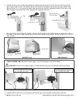
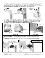
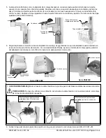
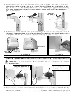
5. Install the M-Series Arm with Mounting Adapter by guiding the Slide (rear of Arm) into the top of the Channel (left
photo below). Slide the Arm to the desired position in the channel and tighten the two (2) set screws (bottom of the
Slide) using the 1/8 in. hex wrench provided (center photo below). Slide the Adjustable Stop #2 to the bottom of the
Slide and tighten the center screw in the Adjustable Stop (right photo below)
.
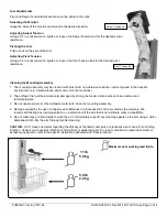
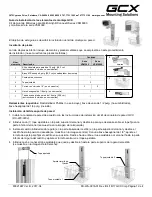
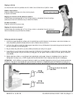
6. Slide the monitor onto the Mounting Adapter, ensuring that the tab at the front of the Adapter is inserted in the slot on
the bottom of the monitor.Tighten the Mounting Screw (rear of the Mounting Adapter) into the threaded hole in the rear
of the monitor.
8. Install the Wall Channel Cover in accordance with the
Channel Cover Installation Guide (DU-UT-0001-20).
Set Screws (2)
M-Series Arm with
Mounting Adapter
Adjustable Stop #2
Slide
Tab
Slot
Mounting Screw
VSM 6000 Series
Mounting Screw
VSM 300 Series
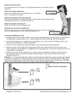
Mount the
Large
Power Supply with
two (2) Hook and Loop Straps.
Mount the
Small
Power Supply with
one (1) Hook and Loop Strap.
7.
(VSM 300 SERIES ONLY)
Mount the power supply on top of Arm using Hook and Loop Straps.
CAUTION:
Do not cover the power supply vent holes with the Strap when mounting the small power supply.