GCD Wi-Pin & Prox Installation And User Manual Download Page 3

4

Installation Diagrams

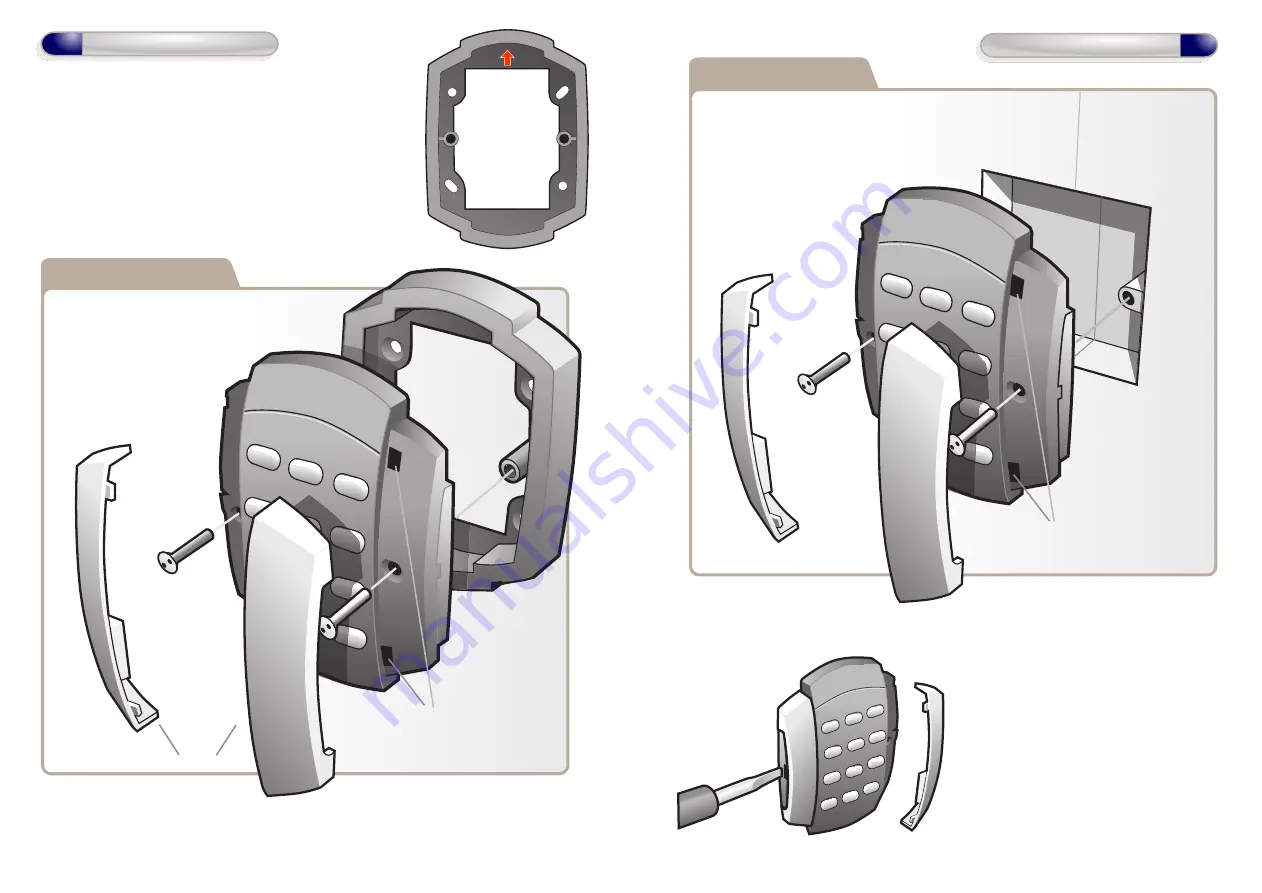
When Surface Mounting the Door Control

a Surface Mount Collar is required.

- Fix Surface Mount Collar to

wall, ensure arrow is

pointing upwards

After fixing Surface Mount Collar to wall
(as above) and wiring is complete as per

wiring diagrams on pages 6-11, the Door
Control may then be screwed to

Surface Mount Collar using
security screws provided.

Both Security Caps are
then clipped onto the Door
Control.

To attach Security Caps: Simply
align the tabs into holes and push

on until click is heard.

Surface Mounting

Security Caps

5

Installation Diagrams

To release Security Caps push a
screwdriver into slots on the side

and pull forward.

Door Control is mounted to electrical pattress box using security
screws provided. Both Security Caps are

then clipped onto Door Control.

Flush Mounting

To attach Security Caps: Simply
align the tabs into holes and push

on until click is heard.

Summary of Contents for Wi-Pin & Prox

Page 1: ...or Controls Wi Pin Prox Wi Pin Wi Prox Other products from GSD Installation User Manual V2 06 Global Security Devices Ltd No 3 Broomhill Business Complex Tallaght Dublin 24 Ireland Phone 353 1 524 269...

Page 2: ...of the Door Control 2 Replace the Defaulting Link Jumper on the Door Control 3 Remove the Defaulting Link Jumper immediately after the Green LED turns ON It will take 5 seconds to switch ON 4 This wi...

Page 3: ...ity screws provided Both Security Caps are then clipped onto the Door Control To attach Security Caps Simply align the tabs into holes and push on until click is heard Surface Mounting Security Caps 5...

Page 4: ...12 24VAC supply Note All OV shown in the diagram are connected to OV of the Door Control 0V 12V 0V NO COM NC 12 24 VAC 12 24 VAC 16V Varistor 12V 0V NO COM NC IP3 IP2 IP1 OP1 OP2 12V Linear Power supp...

Page 5: ...ontact 0V Arm Alarm Input Arm Output N O Alarm Panel Alarm Panel Notes Common OV from the Intruder Alarm Panel and the OV from the Door Control to avoid any ground loop issues Only the Manager User ca...

Page 6: ...0V NO COM NC IP3 IP2 IP1 OP1 OP2 12V Linear Power supply A B TAMP TAMP Interlock OP to Interlock IP on 2nd Door Interlock IP from Interlock OP on 2nd Door Door Contact 0V 0V Door Exit Button Select t...

Page 7: ...efault each Door Control 3 On PC application Doors Tab Click on Add New Door to add a new door to the system 4 Enrolling On a New System Install On PC application Controller Tab Wireless Network Click...

Page 8: ...ed an address all unassigned Door Controls will start to beep the next available address 3 When all doors are assigned Click Secure Network Assigning a Door Address on a Wired 485 Network Step Descrip...

Reviews: