2
Initial Setup
Power Supply
12V DC
Current consumption
70mA
Current consumption with load (max)
100mA
Relay Contact Rating
5 Amps /240V ac
Operating Temperature
-20 C to +60 C
Moisture Resistance
IP 67
Dimensions - Flush Mount
W. 87mm D. 21mm H. 119mm
- Surface Mount W. 87mm D. 35mm H. 119mm
Number of Users
20000
Technical Specs
3
Initial Setup
Factory Default PIN codes
The following PIN codes are the Factory Default Settings on Wi-Pin, Wi-Pin&Prox:
- The Default Engineer code is ‘6666’
- User PIN ‘1111’
Note: The User PIN ’1111’ is deactivated when the Door Control is enrolled
onto a GSD Network Controller.
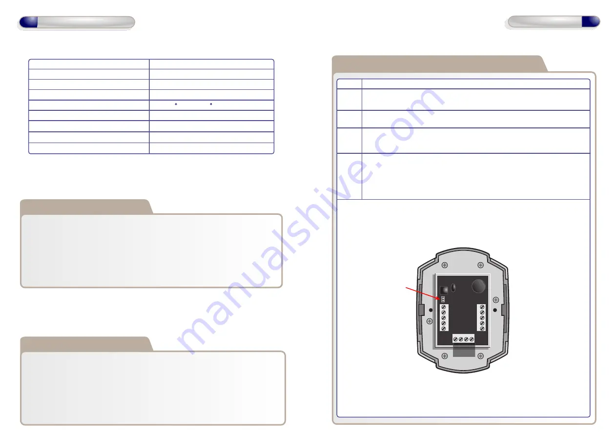
Restoring Factory Settings using Default Link
Step Description
1 Remove the Defaulting Link/Jumper the back of the Door Control.
2 Replace the Defaulting Link/Jumper on the Door Control.
3 Remove the Defaulting Link/Jumper immediately after the Green LED
turns ON. It will take 5 seconds to switch ON.
4 This will cause the Door Control to default, leave it’s current network
and begin scanning to join a new network. The Red LED will flash
rapidly while the Door Control is scanning. The RED LED will switch
ON solid when the Door Control has joined a network.
Initial Installation
The Door Control should be Factory Defaulted after installation. This will restore
all default settings to the Door Control and will unenrol it from any existing GSD
Controller.
The Door Control will then start to scan and enrol on a GSD controller.
Refer to the section ‘Enrolling Door Controls’ for instructions on how to
configure the GSD Windows Software.
12V
0V
NO
COM
NC
IP3
IP2
IP1
OP1
OP2
A
B
T
AMP
T
AMP
Defaulting
Link
Jumper


