


39
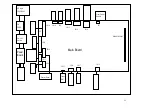
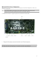
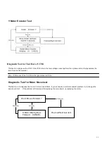
Main board Connection or Replacement
Main board connection or replacement must follow the following steps to be sure that no damage comes to either service
personnel or the components:
Note: To ensure absolute safety for service personnel and components, please follow the safety instruction at the
beginning of this manual, before installing or replacing any current carrying components
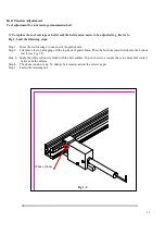
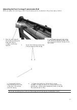
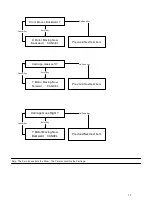
T Parallel Port Connector o unplug the jumpers and connectors from the main board
1. Unplug all of the jumpers and connectors attached to all off board components.
Note: Please refer to the Puma W iring Diagram for more detail on jumper and connector attachment
Y Motor
Y Encoder
Power
Paper 2
X Motor
Y Encoder
LEVEL
Paper 1
Flat cable
Summary of Contents for Puma Series
Page 4: ...4 Main Unit Assembly 29006178G...
Page 7: ...7 Left End Assembly 7 1...
Page 9: ...9 Right End Assembly 7 8...
Page 13: ...13 Complete X motor Assembly 29003820G...
Page 15: ...15 Y Axis Idel Pulley Assembly 29003820G...
Page 17: ...17 Pinch Roller Assembly 29001437G 4 1 8...
Page 19: ...19 Grid Drum Assembly 29005441G...
Page 22: ...22 1 System Diagram and Components of Main Board...


