29
Belt Tension Adjustment
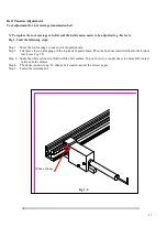
Tool adjustment for tool carriage transmission belt
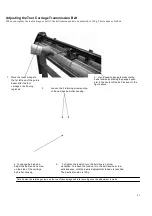
X`To replace the tool carriage or belt it self, the belt tension needs to be adjusted to g . Refer to
Fig 1-5 and the following steps.
Step 1. Move the tool carriage to one end of the guide beam.
Step 2. First place the top arm gauge in the top track of guide beam. Then the bottom arm will click into the bottom
track. (see Fig 1-5)
Step 3. Make the white cylinder is flush with the belt surface. Tug on the wire a couple times to ensure full contact
between both surfaces.
Step 4. The desire tension is 4g. To change belt tension, adjust the screws as per
Step 5. Fasten the retaining nut.
White cylinder
Fig 1-5
Summary of Contents for Puma Series
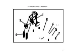
Page 4: ...4 Main Unit Assembly 29006178G...
Page 7: ...7 Left End Assembly 7 1...
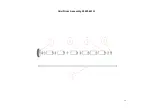
Page 9: ...9 Right End Assembly 7 8...
Page 13: ...13 Complete X motor Assembly 29003820G...
Page 15: ...15 Y Axis Idel Pulley Assembly 29003820G...
Page 17: ...17 Pinch Roller Assembly 29001437G 4 1 8...
Page 19: ...19 Grid Drum Assembly 29005441G...
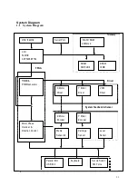
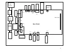
Page 22: ...22 1 System Diagram and Components of Main Board...


