background image

ULTRATHERM 908i

25


gbo Medizintechnik AG 2004

Version 1.6

8


Technical data

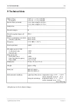
Mains voltage
     On request

230 Vac. +/- 15 %, 50/60 Hz
115 Vac. +/- 15 %, 50/60 Hz

Electric fuses (external)

10 A, slow acting for 230 Vac.
16 A, slow acting for 115 Vac.

Safety class

I

Protection degree

B

Protection against ingress of
liquids:

IP X1

Power consumption, maximum
     Stand-by operation

about 700 W
about 100 W

Frequency

27.12 MHz +/- 0.6 %

Power equivalent

400 W

RF output power at 50 

     Continuous mode,
     Pulsed mode

200 W
30 W

Pulse parameters
     Peak pulse power
     Pulse repetition frequency
     Pulse width

400 W
70 Hz/350 Hz
2 ms / 0.4 ms

Dimensions

85 cm x 38 cm x 39 cm

Weight

approx. 40 kg

Safety test

DIN EN 60601-1
DIN EN 60601-2-3

Environmental conditions

operation of the device: temperature range +10 °C ... +40 °C
                                       relative humidity of air 30 ... 75 %
transport and storage:    temperature range +5 °C ... +50 °C
                                       realtive humidity of air < 90 %,
                                                                           non condensing

All rights reserved for technical changes.

Summary of Contents for ULTRATHERM 908i

Page 1: ...gbo Medizintechnik AG 2004 Version 1 6 Short wave Therapy Unit ULTRATHERM 908i User Manual...

Page 2: ...Art und Weise oder mit welchen Mitteln elektronisch oder mechanisch dies geschieht 2004 gbo Medizintechnik AG The gbo Medizintechnik AG has taken care in preparation of this operating instruction but...

Page 3: ...ilable from the manufacturer or from agencies authorized by the manufacturer The product is intended for a lifetime of 10 years ULTRATHERM 908i is an electronic device Disposing has to be done accordi...

Page 4: ...test level Compliance level Electromagnetic environment guidance Electrostatic discharge ESD IEC61000 4 2 6 kV contact 8 kV air 6 kV contact 8 kV air Floors should be wood concrete or ceramic tile If...

Page 5: ...80 MHz to 800 MHz d 2 3 P for 800 MHz to 2 5 GHz Where P is the maximum output power rating of the transmitter in watts according to the transmitter manufacturer and d is the recommended separation d...

Page 6: ...l standards have not been applied Any change to the product design that is not validated by us will render this declaration invalid Type of product Short WaveTherapy Unit Label ULTRATHERM 908i Options...

Page 7: ...3 1 Mains connection 15 3 2 Switching on 15 3 3 Mode of operation 15 3 4 Choice of the applicator 15 3 5 Connection of the applicators 16 3 6 Treatment time 16 3 7 Setting the dosage 17 3 8 Switching...

Page 8: ...rated by this therapy unit induces a whole range of physiological processes which for example spasmodically influence the muscular system tendons and other connective tissue structures increase the ce...

Page 9: ...cription 2 1 Control panel 1 Power switch with light indicator 2 RESET key 3 Key Continuous mode of operation 4 Key Pulsed mode of operation 70 Hz 2 ms 5 Key Pulsed mode of operation 350 Hz 0 4 ms 6 K...

Page 10: ...which are fitted with brakes that can be actuated for the required stability The top part of the therapy unit is designed as control panel On the panel covered by an easily cleaned and thus user frie...

Page 11: ...25 and plug socket end of the electrode cable into the pin socket 26 underneath 2 4 Applicators and applicator cables Coil as well as capacitor field applicators can be used with the ULTRATHERM 908i s...

Page 12: ...ing side sections it is suitable for large surface treatment and for treatment enclosing the area The twin core electrode cable is permanently screwed to the diplode A ball joint 39 in the centre sect...

Page 13: ...ons The ULTRATHERM 908i conforms to MDD class IIb Due to the strict application of legal standards and rules and maintaining the definitions of the design documentation it complies with the general re...

Page 14: ...distance to other sensitive devices should exceed 5 m if possible and the applicators are not directed to sensitive devices as for instance current stimulators This problem can be completely eliminat...

Page 15: ...The indicators Dosage 15 and Treatment time 14 are lit Further settings are to be made on the keyboard cf figure 3 3 Mode of operation Select the mode of operation with the buttons 3 4 and 5 in the M...

Page 16: ...used in the pulsed mode of operation 3 5 Connection of the applicators Applicators are electrically connected to the sockets 43 Insert the plug pins into the socket up to the stop Please observe that...

Page 17: ...continuous and pulsed modes of operation In order for the therapy unit to deliver the high frequency dosage level selected with dosage knob 17 it is automatically tuned to the patient data after a sho...

Page 18: ...rd 45 Any use of the ripcord is indicated by an intermittent beep sound and FEC appearing on display 15 Switching back to the stand by mode is done by pressing the RESET button 2 3 9 Switching off by...

Page 19: ...be removed because they absorb moisture insufficiently so that local areas with excessive moisture e g skin folds can absorb too much energy and can cause local overheating Before starting the treatm...

Page 20: ...increase with the electric conductivity of the corresponding tissue region tissues with good blood circulation e g muscle tissue and inner organs To reach these deeper tissues the coil applicators of...

Page 21: ...wer and thus for the success of the therapy is the value giver in the dosage display 4 5 Power rating of the applicators The power rating of the individual applicators depends on their surface Overhea...

Page 22: ...pacemakers can extremely be disturbed In these cases the therapy should be only carried out under continuous pulse and ECG control If the patient and or the patient cable is in direct range of a high...

Page 23: ...ll only be replaced by ones of the same rating and type If fuses blow more frequently please contact our after sales service If the error message FE 0 appears on the Dosage display 15 when turning the...

Page 24: ...treatment time buttons 12 13 3 6 Set the dosage knob 17 3 7 Electric power is applied to the output the treatment timer starts operation After the chosen treatment time has elapsed the therapy unit au...

Page 25: ...out 100 W Frequency 27 12 MHz 0 6 Power equivalent 400 W RF output power at 50 Continuous mode Pulsed mode 200 W 30 W Pulse parameters Peak pulse power Pulse repetition frequency Pulse width 400 W 70...

Page 26: ...of 2 Soft rubber plate applicators 8 cm x 14 cm with cable and plug 19 53 413 Q 3236 4 Felt spacer 9 x 16 cm 19 53 272 Q 3236 2 Cloth coating 23 95 606 Q 3236 2 Rubber bands 42 cm 45 38 971 EH 725 4...

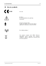
Page 27: ...e operating instructions Connector for patient cable Type B unit suitable for external and internal application to the patient except to the heart Non ionizing radiation This product complies with WEE...

Page 28: ...er pin 26 Pin socket 27 Front cap 28 Back cap 29 Electrode 30 Adjuster pin 31 Slotted bush 32 Locking nut 33 4 fixing holes 34 Guide groove 35 Slotted locking nut 36 Lock electrodes 37 Unlock electrod...

Page 29: ...ULTRATHERM 908i 29 gbo Medizintechnik AG 2004 Version 1 6 R ckseite 27 29 28 34 30 31 33 32 35 38 37 36 41 40 39 42 45 46 43 44...

Page 30: ...rostbite local acute WE SE WE SE M I 3 8 Frostbite local chronic WE SE WE SE M I II 10 Erythema M DI I II 5 10 Furuncle carbuncle M I II 3 5 Hydradenitis SE M II 10 Panaritia WE M DI I II 5 10 Arthrit...

Page 31: ...tis SE DI I III 5 10 Parametritis perimetritis WE WE SE II 5 10 Ovarian insufficiency hypophysis treatment SE II 10 Bronchial asthma SE DI II III 5 10 Bronchiectasis SE DI II III 10 30 Bronchitis SE D...

Page 32: ...echnik AG 2004 Version 1 6 Correction sheet gboAG Dokumentation Kleiststrasse 6 D 64668 Rimbach Germany Please revise the following errors and stimulation to the document page line wrong text right te...

Reviews: