background image

18     Gateway ALR 9000 User’s Guide

Expansion Slots

There are a total of twelve expansion slots on the system board: 

seven 32-bit PCI slots

four 32-bit EISA slots

one shared PCI/EISA slot

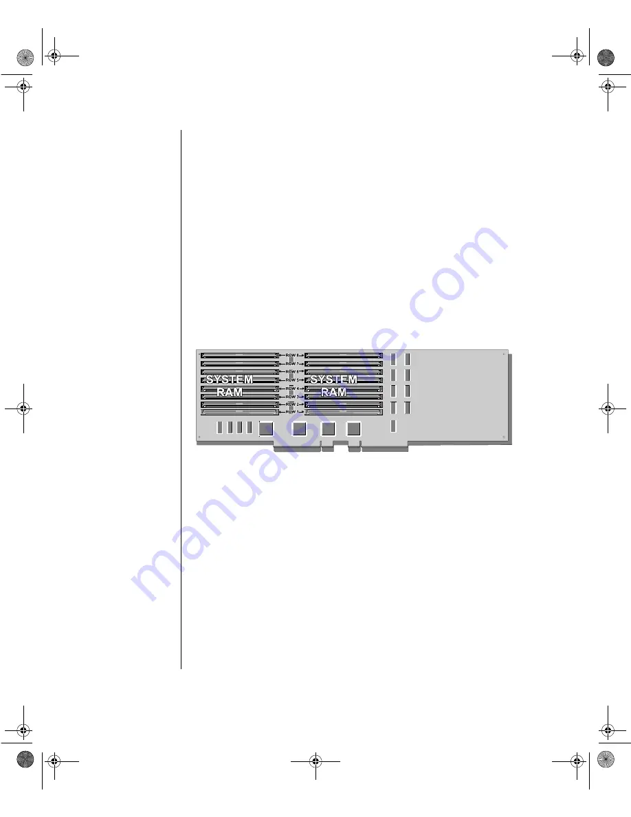
Memory 

The system comes standard with 128-MB Error and Correction (ECC) 
RAM installed on the SIMM card.  The sixteen SIMM sockets (8 rows/
banks) can support up to 2-GB of ECC memory.  The optional 2 card 
supports up to 4-GB of ECC memory.

InforManager™

The system is equipped with InforManager (IFM), a special feature 
consisting of both hardware and software designed to monitor and report 
the operation status of the system and its devices: CPUs, power supplies, 
RAM, ambient temperatures, voltages, and fan operation.  One way to 
monitor these devices is using the InforManager LCD panel (see Chapter 
3).  

Also supplied with this system are client-server monitoring utilities with 
two special features (currently available in the Windows NT™ utilities 
only):

Figure 6:  Memory Card

USRGUIDE.BOO  Page 18  Thursday, July 16, 1998  10:41 AM

Summary of Contents for ALR 9000

Page 1: ...7 98 In our effort to use nature s resources efficiently and wisely we print all manuals on recycled papers that meet the minimum requirements established by the Federal EPA in its guidelines for rec...

Page 2: ...ntel Intel Inside logo and Pentium are registered trademarks and MMX is a trademark of Intel Corporation Microsoft MS MS DOS and Windows are trademarks or registered trademarks of Microsoft Corporatio...

Page 3: ...4 Powering Up the System 5 System Features 7 Basic Architecture 8 Front Panel 9 Reset Switch 9 3 5 inch Floppy Disk Drive 9 SCSI CD ROM Drive 9 Bezel Doors 10 Storage Bays 10 Keyboard Inhibit Switch 1...

Page 4: ...orManager LCD 21 About InforManager 22 CPU Menu 24 RAM Menu 25 Disk Activity Menu 26 Fan and Temperature Menu 27 Power Menu 28 Lock Menu 29 System Menu 30 LCD Reset 31 ID Setup 32 Alarm ID Speaker Men...

Page 5: ...v Cleaning the Keyboard 45 Cleaning the Monitor Screen 45 Index IN 47 USRGUIDE BOO Page v Thursday July 16 1998 10 41 AM...

Page 6: ...vi Gateway ALR 9000 User s Guide USRGUIDE BOO Page vi Thursday July 16 1998 10 41 AM...

Page 7: ...e the total ampere ratings on the products plugged into the extension cord do not exceed the extension cord ampere rating Also the total ampere requirements for all products plugged into the wall outl...

Page 8: ...circuit different from that to which the receiver is connected Consult the dealer or an experienced radio TV technician for help Accessories This equipment has been tested and found to comply with th...

Page 9: ...73 23 EEC as per EN 60950 1992 This is a Class A product based on the standard of the Voluntary Control Council for Interference by Information Technology Equipment VCCI If this equipment is used in a...

Page 10: ...s inactive until the infected program is executed or a boot record is read Thereafter the virus loads itself into system memory and begins to copy and spread itself Diskettes used in a contaminated sy...

Page 11: ...drives CD ROMs floppies boot sectors and partition tables VirusScan also provides advanced protection against unknown viruses We continuously update and use the most current version of McAfee VirusSca...

Page 12: ...xii Gateway ALR 9000 User s Guide USRGUIDE BOO Page xii Thursday July 16 1998 10 41 AM...

Page 13: ...Preface Preface Contents About This Guide xiv Conventions Used in this Guide xv USRGUIDE BOO Page xiii Thursday July 16 1998 10 41 AM...

Page 14: ...ures covers information about the internal and external features as well as the system architecture and supported operating systems Chapter 3 InforManager LCD discusses the IFM display with details ab...

Page 15: ...he keys on either side of it must be pressed simul taneously Setup Commands to be entered as well as messages that appear on your monitor are printed in ARIAL font System User s Guide Names of publica...

Page 16: ...xvi Gateway ALR 9000 User s Guide USRGUIDE BOO Page xvi Thursday July 16 1998 10 41 AM...

Page 17: ...Chapter 1 Getting Started Contents Before You Begin 2 Assembling Your System 3 Connecting Peripherals 4 Powering Up the System 5 USRGUIDE BOO Page 1 Thursday July 16 1998 10 41 AM...

Page 18: ...system you are probably eager to assemble and have it operating This section will help you accomplish the following Assemble the system Connect your monitor and keyboard Power up the system Carefully...

Page 19: ...the contents Standard systems include the following items Check the packing list to verify that all equipment and associated manuals are included in your shipment Inspect everything carefully If you...

Page 20: ...your system 3 Connect the monitor power cable to an AC outlet or preferably a surge control outlet station 4 Verify that the Voltage Selection Switch on each power supply is set for the proper voltag...

Page 21: ...quence If more than one CPU is installed the system will display which CPU it is currently testing If any errors are encountered your system will display them on the monitor If a monitor is not connec...

Page 22: ...6 Gateway ALR 9000 User s Guide USRGUIDE BOO Page 6 Thursday July 16 1998 10 41 AM...

Page 23: ...Chapter 2 System Features Contents Basic Architecture 8 Front Panel 9 Rear Panel 12 System Board 15 USRGUIDE BOO Page 7 Thursday July 16 1998 10 41 AM...

Page 24: ...rocessors and memory 256 bit with 4 way memory interleave 2 MB DRAM PCI graphics adapter SCSI CD ROM drive 1 44 MB 3 5 inch floppy drive Integrated floppy drive controller supporting up to two floppy...

Page 25: ...ng to power it off and then on again 3 5 inch Floppy Disk Drive The standard system is equipped with one half height 1 44 MB 3 5 inch floppy disk SCSI CD ROM Drive The system comes standard with one f...

Page 26: ...t accessible and can support any 5 25 inch device or 3 5 inch device with a special mounting bracket six 3 5 inch Quick Hot Swap bays housed in a RAIDCage RAIDCage 6D which also supports 1 inch and 1...

Page 27: ...ays the status of the InforManager and allows the user access to all of its functions System Monitor Fan Monitors Temperature Monitors Power Supply Monitors Activity Monitors CPU and disk drives Rear...

Page 28: ...ectors and switches as illustrated and explained below ECC Reset Switch This switch allows you to reset the system when a memory fault occurs Parallel Port Connect parallel devices such as parallel pr...

Page 29: ...ch as serial printers or modems can also be connected this port Power Supply Fault Reset Switch In the event of a power supply failure pressing this switch turns off the alarm signal and resets the po...

Page 30: ...nstallation or replacement of the power supply AC In Power Connector A This socket conveys power to power supplies 1 and 2 Connect the system power cable to this socket and to an AC outlet AC In Power...

Page 31: ...m Board The system board functions as the main interface between the processor memory and peripherals Below is an illustration of the system board Figure 4 System Board USRGUIDE BOO Page 15 Thursday J...

Page 32: ...nterrupts access system memory and perform I O operations If your operating system does not support SMP the system adjusts the processing mode to Asymmetrical meaning only the first CPU accepts I O in...

Page 33: ...mizing data transfer on PCI local bus at 133 MB sec data bursts BIOS Developer s Kit BDK allowing easy customization of system BIOS code for various features SCAM SCSI Configured Automatically Level 1...

Page 34: ...4 GB of ECC memory InforManager The system is equipped with InforManager IFM a special feature consisting of both hardware and software designed to monitor and report the operation status of the syste...

Page 35: ...om damage from extreme temperatures and voltages Server Watchdog monitors the system for hangups and reboots after a designated period of time For detailed information about the InforManager utilities...

Page 36: ...20 Gateway ALR 9000 User s Guide USRGUIDE BOO Page 20 Thursday July 16 1998 10 41 AM...

Page 37: ...About InforManager 22 CPU Menu 24 RAM Menu 25 Disk Activity Menu 26 Fan and Temperature Menu 27 Power Menu 28 Lock Menu 29 System Menu 30 Alarm ID Speaker Menu 33 System Tolerances 34 USRGUIDE BOO Pag...

Page 38: ...Temperature Monitors System Power and Power Supply Monitors Activity Monitors CPU and disk drives Side Panel Monitors System Information To access any menu screen gently touch the icon of the device y...

Page 39: ...screens programmed on the LCD panel Refer to the following sections for more specific information about each menu screen Figure 7 Diagram of LCD Menus Important A flashing button on the Main menu scre...

Page 40: ...Gateway ALR 9000 User s Guide CPU Menu The CPU menu displays the status Good or Fail and current activity Idle or Busy of each CPU Figure 8 CPU Menu USRGUIDE BOO Page 24 Thursday July 16 1998 10 41 A...

Page 41: ...Menu The RAM menu displays the current amount of RAM and its status Good or Fail The ECC Error Reset button is also accessible through this menu Figure 9 RAM Menu USRGUIDE BOO Page 25 Thursday July 1...

Page 42: ...Activity Menu The Disk Activity menu displays the drives currently installed and their activity which is indicated by a double dash underneath BUSY or IDLE Figure 10 Disk Activity Menu USRGUIDE BOO P...

Page 43: ...adout will begin to flash instead A submenu displays the temperature of each CPU as well as the internal and external ambient temperatures Normal temperature is indicated by the continuous rising and...

Page 44: ...voltages supplied to the peripherals When a voltage is within normal range the pointer in the voltage meter icon moves laterally back and forth If an out of range voltage occurs the pointer will stop...

Page 45: ...nu displays the status OPEN CLOSE of the side panels A flashing icon indicates that the corresponding panel is open When a panel is closed the icon remains static Figure 13 Lock Menu USRGUIDE BOO Page...

Page 46: ...lled are displayed on this menu Communication between the LCD and IFM is designated by the continuously increasing and decreasing number of dashes underneath the LCD HOST IFM Communication line Non co...

Page 47: ...Reset button which is accessible through the Main screen submenu as shown below 2 If there is still no communication between the LCD and host IFM then reboot the system 3 If there is still no communic...

Page 48: ...board In the event these ID numbers do not match communication will cease You must restore communication by performing the following 1 Press the Reload ID button to automatically reload an LCD ID num...

Page 49: ...ID Speaker Menu The Alarm Menu allows you to turn the speaker OFF or ON The default is ON You can also access ID Setup and LCD Reset from this menu Figure 16 Alarm ID Speaker Menu USRGUIDE BOO Page 33...

Page 50: ...78 95 external ambient tempera ture drivecage 98 95 122 drive cage temperature systemboard3VP 3 0 3 3 3 6 system board voltage 3 3V systemboard5VP 4 5 5 0 5 5 system board voltage 5 0V systemboard5VN...

Page 51: ...ts Handy Checklists 36 Looking Things Over 36 Verifying Your Configuration 36 Common Problems 37 Drive Problems 38 Monitor Problems 39 Printer Problems 40 Installation Problems 41 USRGUIDE BOO Page 35...

Page 52: ...em perform the following checks 1 Is the power cord connected to the PC and an AC outlet 2 Is the AC outlet supplying power 3 If a power strip is used is it switched on 4 Are the voltage selection swi...

Page 53: ...incorrectly Enter the BIOS Setup program and correct the date and time settings The backup battery may need to be replaced Contact Technical Support for assistance The Power LED is flashing ECC memory...

Page 54: ...upted bad Try the diskette on another computer Re copy the file if necessary Files cannot be written to the disk or diskette The disk is write protected Remove the write protect tab or switch from the...

Page 55: ...able is not connected to the system s video port Check the video cable and ensure it is connected to the proper port The video cable s connec tor has a bent pin Check the cable s connector and repair...

Page 56: ...nd make cer tain it is connected to the cor rect port The printer s data cable is damaged Check the cable for bent pins or broken wires The port is bad Call Technical Support The printer prints garbag...

Page 57: ...the DIMMs for proper installation A memory DIMM is not functioning properly Replace the faulty DIMM An adapter card is not recognized by the system The interrupt and or I O address is set incorrectly...

Page 58: ...42 Gateway ALR 9000 User s Guide USRGUIDE BOO Page 42 Thursday July 16 1998 10 41 AM...

Page 59: ...Chapter 5 Maintenance Contents Cleaning the Mouse 44 Cleaning the Keyboard 45 Cleaning the Monitor Screen 45 USRGUIDE BOO Page 43 Thursday July 16 1998 10 41 AM...

Page 60: ...at secure the cover Set aside screws 3 Remove the ball out of the ball socket 4 Use adhesive tape to pick up any dust or lint on the surface of the mouse ball 5 With a cleaning cloth wipe away dirt or...

Page 61: ...w 1 Shut down the computer and disconnect the keyboard 2 Turn the keyboard upside down for the liquid to drain out Allow the keyboard to dry overnight before trying to use it again 3 After verifying t...

Page 62: ...46 Gateway ALR 9000 User s Guide USRGUIDE BOO Page 46 Thursday July 16 1998 10 41 AM...

Page 63: ...27 firmware 30 Flash BIOS 8 floppy disk 9 floppy drive 8 10 16 format 41 front panel 9 11 22 G graphics adapter 8 H host IFM 31 humidity 3 I I O Ports 12 keyboard port 4 printer port 40 video port 4 I...

Page 64: ...reset switch 9 Return Material Authorization RMA 3 36 S SCSI 8 9 10 serial port 13 Serial printers 40 SIMM 8 SMP 16 speaker 33 storage bays 10 quick hot swap 10 switch ECC reset 12 keyboard inhibit 1...

Reviews: