


G4-508HD4a User Manual & Install Guide
Hardware Installation
147 of 162
Installation Guidelines
Please note the following:
§
The device must be secured to an interior surface of the vehicle using the Tek Screws provided.
§
DO NOT orient the device such that the drive caddy handle faces the floor of the vehicle.
§
Wire the device into the vehicle according to the Quick Reference Guide and the appropriate cabling
diagram.
§
DO NOT disassemble the device. There are no user serviceable parts inside.
Configuration Guidelines
§
The device firmware must be configured before using the DVR.
§
Connect a monitor to the A/V out jack on the front of the device or an ICD2 to the ICD2 connection on
the rear of the DVR.
§
Press the Setup key on the IR Remote Control (below the directional arrow pad)
§
Enter the following login information when prompted:
User name
: admin
Password
: admin
§
You can also use the ICD2’s touch screen to perform these tasks starting with the Menu button.
§
Move the cursor to the Setup icon and press Enter.
§
Navigate to
Surveillance>Record>Mainstream
to setup the analog channels (one through eight).
§
To set up IP Channels (nine through twelve), navigate to
Surveillance>IPC Setup
and select Fast Setup
and bind the IP cameras to channels nine through twelve.
§
To set Vehicle ID, navigate to
Basic Setup>Regist Info>Vehicle Info
.
§
After setting the configurations, with the Hard Drive (and optional SD Card) inserted, access the Setup
menu. Navigate to
Setup>Maintenance>Storage
to format the drive(s).
Please note, non-Gatekeeper branded SD cards may not function reliably. If used, non-
Gatekeeper branded SD cards must be formatted in the DVR prior to use.
§
Start vehicle, and wait for recorder to boot up (approximately two minutes). Confirm live camera
video is visible on monitor (small Green camera in each camera image – indicates the DVR is
recording).
§
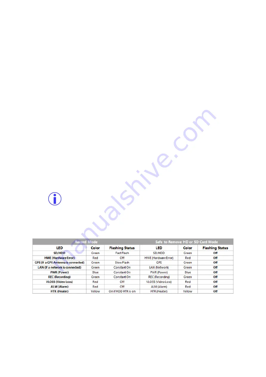
Confirm DVR is recording by observing the LED’s as per the following table.
Note: The LAN status LED is currently not supported.
§
To access the SD card, turn key to unlock position, open SD card slot door (to the right of the hard
drive) and only remove SD card when the BLUE power light is NOT illuminated (refer to the table to
determine when it is safe to remove the SD card).
§
Your device is ready to go!


