

www.gastron.com
10
_
11
GTC-550
Instruction Manual
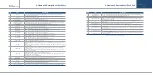
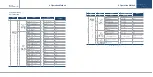
No
ITEMS
SPECIFICATION
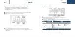
1
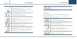
Case cover
It is made of ABS Material. It fixes the display and protects the circuit from surrounding
environment and external shock.
2
Case body
It is made of ABS Material. It fixes the Main PCB and protects the circuit from surrounding
environment and external shock.
3
Warning Light
Upon an event of error, the warning light turns on.
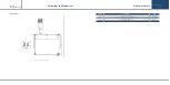
4
Mount hole(2-Ø6.5)
It is a hole to fix the control unit to an external wall or other mount plate.
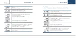
5
Conduit connection
(1-Ø16.5, 5-Ø20.5)
6 holes each of Ø16.5 and Ø 20.5 are set at the bottom part. Depending on the site condition,
power cable, signal cable, etc. are connected using cable inlet.
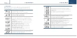
6
O - Ring <NBR>
It works as waterproofing material to prevent rainwater from entering inside.
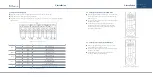
7
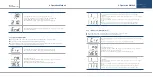
Power LED
When power is inputted, the power LED lights on.
8
Stand-by LED
When the detector is in stand-by mode, STD-BY LED blinks.
9
Fault LED
(Trouble LED)
Upon an event of trouble in receiver unit and detector part, the trouble LED lights on.
Ex.) * Poor wiring with the detector and an event of error
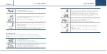
10
Alarm 3 LED
When the tertiary alarm occurs, Alarm 3 LED lights on.
When it reaches Alarm 3 threshold during a test, Alarm 3 LED lights on.
11
Alarm 2 LED
When the secondary alarm occurs, Alarm 2 LED lights on.
When it reaches Alarm 2 threshold during a test, Alarm 2 LED lights on.
12
Alarm 1 LED
When the primary alarm occurs, Alarm 1 LED lights on.
When it reaches Alarm 1 threshold during a test, Alarm 1 LED lights on.
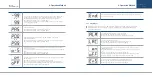
13
"FUNC" S/W
"FUNC" S/W is a key to change and select then enter data for alarm threshold, alarm type, alarm
dead band, and alarm dwell time settings, etc.
14
"UP" S/W
After selecting each mode using "FUNC" S/W, use to increase the set value or to select the next
setting.
When a value needs to be changes in a large range, pressing "UP" S/W for a certain time changes
the value rapidly.
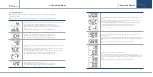
15
"DOWN" S/W
After selecting each mode using "FUNC" S/W, use to decrease the set value or to select the
previous setting.
When a value needs to be changes in a large range, pressing "DOWN" S/W for a certain time
changes the value rapidly.
16
"TEST" S/W
Pressing "TEST" S/W enters a mode that performs self-test.
Measurement FND flickers and the value can be adjusted using "UP" S/W and "DOWN" S/W to
check the alarm operation status.
To release self-test, press "RESET" S/W.
17
"RESET" S/W
Performs functions to release alarm, self-test, and program setting, etc.
18
"BZ-STOP" S/W
Used to stop the buzzer upon an event of alarm
19
Buzzer
Operates in a continuous tone upon an event of warning or fault during a test.
20
LCD PCB Ass'y
Displays measurement from detector in a continuous manner.
During test, it displays user defined value with flickering.
21
Terminal Block Cover
To supply power to the equipment, open the terminal block cover and connect power cable.
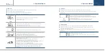
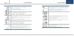
No
ITEMS
SPECIFICATION
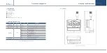
22
RS-485 Network
Module(Option)
RS-485 network module is isolated type that connects PC and other external network devices to
receive and transmit the current concentration and settings, etc.
23
SMPS
Converter that converts 220V-AC to 24V-DC power.
24
Power ON/OFF S/W
S/W used to turn ON and OFF of the control unit power. When performing cable wiring work,
power must be turned OFF.
25
Fuse
Works as a breaker to protect the equipment by cutting fuse with heat generated from
overcurrent.
26
Power Input Terminal
Terminal for power cable connection for operation of the control unit.
27
External Warning Light
Power Terminal
Assistance power terminal for installation of external warning light during operation of the
control unit.
28
Signal output terminal
Used for Relay Dry Contract Signal such as warning, failure, etc. and connecting Switch Signal
Output Cable, etc.
29
Signal I/O terminal
Used for connecting cables for power supply of gas leak detector, 4~20 mA current output, and
RS-485 MODBUS Network, etc.
30
Cover Fixing Hook
Device to fix the cover on the case body. To open the cover, push the hook and pull the cover
towards the front.
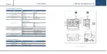
[Table 1. GTC-540 Configuration Description]
4. Name and Description of Each Part
4. Name and Description of Each Part


