


-5-
Radio Setup
On this section you can program the radio inputs to mach your transmitter and setup
the brake power.
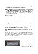
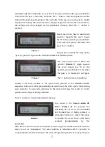
First screen is the
Gear Up
position (
Picture 3
):
Set the transmitter switch or slider of the gear
channel in the position you wish that the gear be
in retracted position. Current reading is displayed
on the right side of the screen. Once the TX is set,
press the “+” button. The controller will store
the current signal received as “
gear up
” command.
Next screen is the
Gear Down
position:
Set the transmitter switch or slider of the gear channel in the position you wish that the
gear be in extended position. Once the TX set, press the “+” button. The controller will
store the current signal received as “gear down” command.
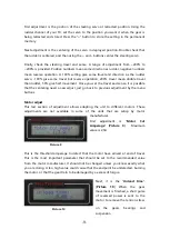
Next screen is the
Brake OFF
position:
Set the transmitter switch or slider of the brake channel (or on the gear channel if you
use the single channel option) in the position you
wish that the brake be unpowered. Press the “+”
button.
The controller will store the current
signal received as “
Brake OFF
”
command (
Picture 4
). Note that if in this step the controller does not detect a valid
signal in the brake input, then it will assume a single channel operation mode, To enable
double channel, this step should be repeated once the brake channel is connected to a
valid RC signal source.
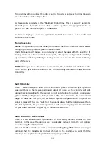
Last radio screen is the Brake Maximum position.
Set the transmitter switch or slider of the brake channel (or on the gear channel if you
use the single channel option) in the position you wish that the brake be at maximum
power. Press the “+” button. The controller will store the current signal received as
“
Brake 100%” command”.
This completes the radio setup for the gear and brake channels. But two more adjust
options are offered in this section:
Picture 3
Picture 4


