Gaspar Xicoy LGC 13C User Manual Download Page 10

-9- 


First  adjustment  is  the  position  of  the  steering  servo  at  retracted  position.  Using  the 
rudder  channel of your  TX, set the  servo  to the  position you want it when the gear is 
being retracted and stored. Press the “+” button to store the setting in the permanent 
memory. 
 
Next adjustment is the centering of the servo in deployed position. Double check that 
the rudder is centered, and then using the + and – buttons center the steering servo. 
 
Finally,  check  the  steering  travel  and  sense.  A  range  of  adjustment  from  –200%  to 
+200% is provided. Positive numbers mean same direction as rudder, negative numbers 
mean  reverse  operation.  A  100%  setting  give  same  travel  and  direction  as  the  rudder 
servo,  -100%  give  same  travel  but  reverse  operation,  200%  travel  mean  double  travel 
than rudder, 50% give half movement. Once you set the travel and sense, it is possible 
that the centering need a new adjust, just go back to previous adjustment by the menu 
buttons.  
 

Motor adjust 

This  last  section  of  adjustment  allows  adapting  the  unit  to  different  motors.  These 
adjustments  are  not  available  in  some  of  the  units  that  are  setup  by  motor 

manufacturer. 
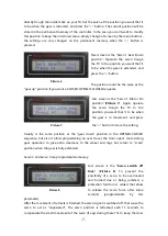
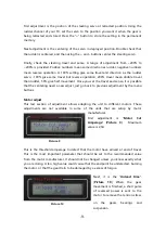
First  adjustment  is  “

Motor  Cut 

Amperage

”  (

Picture  9

).    Maximum 

value is 2,5A.  


This is the  threshold amperage to detect that the motor have arrived at end of travel. 
This  is  the  most  important  parameter  that  should  be  set  to  the  recommended  value 
from the motor manufacturer. It should not be changed unless you know exactly what 
you are doing. A too high value could cause that the endpoint be undetected, burning 
the motor, or that the gear train to be damaged by a excess of torque. 
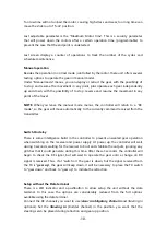
 
Next,  it  is  the  “

Unload  time

”. 

(

Picture  10

)  When  the  gear 

movement is finished, a short pulse 
of  reversed  power  is  sent  to  the 
motor to remove the tension stress 

on  the  gears,  bearings  and 
suspension.  

Picture 9 

Picture 10 

Summary of Contents for Xicoy LGC 13C

Page 1: ...LGC 13C Users Guide Plaça Pere Llauger I Prim nau 18 08360 Canet de Mar Barcelona Catalonia Spain E mail sales xicoy com Fax 34 93 794 27 74 web www xicoy com Copyright 2019 Xicoy Electronica SL All Rights Reserved Manual contents design Gaspar Espiell ...

Page 2: ...retracted mode programmable center sense of movement and gain on extended position Single or dual channel mode Programmable delay for extension and retraction of all gears independently Easy programming trough a LCD display Small size and lightweight Installation Thanks the small size and lightweight of the unit it can be placed in any place on the model We recommend a place where the wiring to th...

Page 3: ...s beyond repair Output for the door servos Connect the 3 servos to the outputs on the unit You can connect more than one servo to each output using a Y lead Output to the steering servo Connect the steering servo to Steer Out if used Radio inputs You can choose to use a single channel to control the gear and brake or separated channels Gear input channel should be always connected for operation br...

Page 4: ...xcessive causing the receiver to switch off c The power input pin of the Gear and Brake inputs are internally connected together This could cause a malfunction by connecting different voltages together For example if you connect the Gear Input directly to the receiver that is powered at 5V and the brake input to a battery regulator that supply 6V then the 6V supply will flow trough the unit to the...

Page 5: ...oy data terminal please jump to the Manual Setup section for the pushbutton and Led setup procedure Setup using a data terminal Connect the data terminal Same model as used by Xicoy V10 ecus on the socket at left side of Gear In input You can navigate trough the different menus by the buttons on the left side of the box and values are changed using the and buttons on the right side First screen di...

Page 6: ...ter switch or slider of the brake channel or on the gear channel if you use the single channel option in the position you wish that the brake be unpowered Press the button The controller will store the current signal received as Brake OFF command Picture 4 Note that if in this step the controller does not detect a valid signal in the brake input then it will assume a single channel operation mode ...

Page 7: ...fferent positions for each output Gear Up position The position you wish that the servo be driven when the gear is retracted Typically is a closed door Gear Down position The position you wish that the servo be driven when the gear is extended Depending on model type could be a opened or closed door Motor ON position The position of the doors when the retracts are moving typically open The setup o...

Page 8: ...h the TX to the position you want that it to be when the gear is in movement and press the button to store the setting Usually is the same position as the gear down position in the OPENED CLOSED sequence but also it allow programming an over travel the door opens more during gear operation to give extra clearance to the wheel and legs but return to scale position when the gear is fully extended Se...

Page 9: ...r is operated since the Gear Up command is selected Second screen is the delay time on the same gear main left motor operation when gear down is selected Next screens adjust same delays for right mains and nose gear Please note that you can use this function to insert a delay from door operation to gear operation by programming same delay on all 3 motors Steering servo processor The steering servo...

Page 10: ...the travel and sense it is possible that the centering need a new adjust just go back to previous adjustment by the menu buttons Motor adjust This last section of adjustment allows adapting the unit to different motors These adjustments are not available in some of the units that are setup by motor manufacturer First adjustment is Motor Cut Amperage Picture 9 Maximum value is 2 5A This is the thre...

Page 11: ...e currently command received from the transmitter Switch On delay There is some intelligence build in the controller to prevent unwanted gear operation when switching on the receiver and power supply At power up the controller will wait during 3 seconds waiting for the receiver to boot and stabilize the outputs ignoring any glitches that it could generate during this time After these 3 seconds the...

Page 12: ...nit will detect if signal present on Brake In if not will assume single channel mode 4 blinks Brake maximum 5 Blinks Steering servo retracted position NOTE Executing this procedure will set all remaining adjustments to the factory defaults all delays door servo positions steering servo adjustments will be reset to default This procedure allow to use the controller in simple models without the need...

Reviews: