Gaspar Xicoy LGC 13C User Manual Download Page 12

-11- 


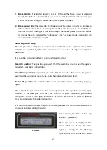
Leave the main battery disconnected to prevent accidental movement of motors. 
 

Switch  off  the  power

.  Press  the  button  with  the  aid  of  a  plastic  rod  (a  pen,  etc,  but 

nothing  metallic  that  could  damage  the  electronic  board).  While  the  button  pressed, 
switch on the power on the receiver. 
 
When receiver powered, release the switch. 
 
The blue LED will light intermittently, one short flash with a long pause between flashes.  
Set your transmitter at the position you want the gear to be retracted. 
Once the TX set, press the switch again. Hold it pressed until it lit continuously, this will 
indicate that the command received from the TX as been stored as “

Gear Up

” command. 

Release the button, the led will blink 2 short times followed by a long pause. Repeat the 
procedure described above for to memorize the remaining radio commands: 


1 blink 


Gear Up

 command 


2 blinks 


Gear Down

 (extended) command 


3 blinks 


Brake OFF

. The unit will detect if  signal present on  Brake In,  if not will 

assume single channel mode. 


4 blinks 


Brake maximum


5 Blinks 

 Steering servo retracted position.   


NOTE

:  Executing  this  procedure  will  set  all  remaining  adjustments  to  the  factory 

defaults,  all  delays,  door  servo  positions,  steering  servo  adjustments  will  be  reset  to 
default.  This procedure allow to use the controller in simple models without the need of 
a data terminal. 
 

Disposal 

Electrical equipment marked with the cancelled waste bin symbol 

must not be 

discarded in the standard household waste; instead it must be taken to a suitable 
specialist disposal system.


In the countries of the EU (European Union) electrical equipment must not be discarded 
via  the  normal  domestic  refuse  system  (WEEE  -  Waste  of  Electrical  and  Electronic 
Equipment,directive  2002/96/EG).  You  can  take  unwanted  equipment  to  your  nearest 
local  authority  waste  collection  point  or  recycling  centre.  There  the  equipment  will  be 
disposed of correctly and at no cost to you. 
 
By returning your unwanted equipment you can make an important contribution to the 
protection of the environment.


Summary of Contents for Xicoy LGC 13C

Page 1: ...LGC 13C Users Guide Plaça Pere Llauger I Prim nau 18 08360 Canet de Mar Barcelona Catalonia Spain E mail sales xicoy com Fax 34 93 794 27 74 web www xicoy com Copyright 2019 Xicoy Electronica SL All Rights Reserved Manual contents design Gaspar Espiell ...

Page 2: ...retracted mode programmable center sense of movement and gain on extended position Single or dual channel mode Programmable delay for extension and retraction of all gears independently Easy programming trough a LCD display Small size and lightweight Installation Thanks the small size and lightweight of the unit it can be placed in any place on the model We recommend a place where the wiring to th...

Page 3: ...s beyond repair Output for the door servos Connect the 3 servos to the outputs on the unit You can connect more than one servo to each output using a Y lead Output to the steering servo Connect the steering servo to Steer Out if used Radio inputs You can choose to use a single channel to control the gear and brake or separated channels Gear input channel should be always connected for operation br...

Page 4: ...xcessive causing the receiver to switch off c The power input pin of the Gear and Brake inputs are internally connected together This could cause a malfunction by connecting different voltages together For example if you connect the Gear Input directly to the receiver that is powered at 5V and the brake input to a battery regulator that supply 6V then the 6V supply will flow trough the unit to the...

Page 5: ...oy data terminal please jump to the Manual Setup section for the pushbutton and Led setup procedure Setup using a data terminal Connect the data terminal Same model as used by Xicoy V10 ecus on the socket at left side of Gear In input You can navigate trough the different menus by the buttons on the left side of the box and values are changed using the and buttons on the right side First screen di...

Page 6: ...ter switch or slider of the brake channel or on the gear channel if you use the single channel option in the position you wish that the brake be unpowered Press the button The controller will store the current signal received as Brake OFF command Picture 4 Note that if in this step the controller does not detect a valid signal in the brake input then it will assume a single channel operation mode ...

Page 7: ...fferent positions for each output Gear Up position The position you wish that the servo be driven when the gear is retracted Typically is a closed door Gear Down position The position you wish that the servo be driven when the gear is extended Depending on model type could be a opened or closed door Motor ON position The position of the doors when the retracts are moving typically open The setup o...

Page 8: ...h the TX to the position you want that it to be when the gear is in movement and press the button to store the setting Usually is the same position as the gear down position in the OPENED CLOSED sequence but also it allow programming an over travel the door opens more during gear operation to give extra clearance to the wheel and legs but return to scale position when the gear is fully extended Se...

Page 9: ...r is operated since the Gear Up command is selected Second screen is the delay time on the same gear main left motor operation when gear down is selected Next screens adjust same delays for right mains and nose gear Please note that you can use this function to insert a delay from door operation to gear operation by programming same delay on all 3 motors Steering servo processor The steering servo...

Page 10: ...the travel and sense it is possible that the centering need a new adjust just go back to previous adjustment by the menu buttons Motor adjust This last section of adjustment allows adapting the unit to different motors These adjustments are not available in some of the units that are setup by motor manufacturer First adjustment is Motor Cut Amperage Picture 9 Maximum value is 2 5A This is the thre...

Page 11: ...e currently command received from the transmitter Switch On delay There is some intelligence build in the controller to prevent unwanted gear operation when switching on the receiver and power supply At power up the controller will wait during 3 seconds waiting for the receiver to boot and stabilize the outputs ignoring any glitches that it could generate during this time After these 3 seconds the...

Page 12: ...nit will detect if signal present on Brake In if not will assume single channel mode 4 blinks Brake maximum 5 Blinks Steering servo retracted position NOTE Executing this procedure will set all remaining adjustments to the factory defaults all delays door servo positions steering servo adjustments will be reset to default This procedure allow to use the controller in simple models without the need...

Reviews: