background image

7

WIRING DIAGRAM

Make sure You have a good chassis ground. Good ground connection will eliminate 
most electrical noise problems. A good chassis ground requires a tight connection to the 
vehicle’s metal chassis. The area around the ground connection should be clean, bare 
metal without rust, paint, plastic, dust, or dirt for a good ground connection. 
Black Ground
Connect to vehicle body/chassis. Make sure you have a good chassis ground. This will 
eliminate most electrical noise form the motor and alternator. A good chassis ground 
requires a tight connection to ground. The area should be free from rust, paint or any 
form of dirt.
Yellow Memory Backup
Connect to electrical terminal always supplied with power regardless of ignition switch 
position.
Orange Remote
Connect to Auto-antenna or power amp control wire/remote  connection. Maximum cur-
rent 300mA 12VDC. (Low Current)

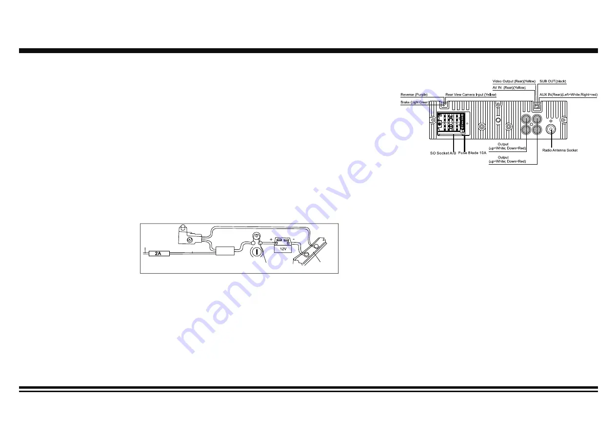
Parking wire connection

Speaker Wiring Notes:

Follow the above wiring diagram to install the head unit with new or existing speakers.
1. This unit is designed for use with four (4) speakers with impedance between 4 Ohms to 8 Ohms.
2. An Impedance load of less than 4 Ohms could damage the unit.
3. Never bridge or combine the speaker wire outputs. When not using four speakers, use electrical tape to tape the ends of the unused 
speaker outputs to prevent a short circuit.
4. Never ground the negative speaker terminals to chassis ground.

RCA

RCA

Connector A

1. Rear right s)/Purple
2.
3. Front right s)/Grey

5. Front left s)/White

Rear right speaker(-)/Purple-Black

4. Front right speaker(-)/Grey-Black

6. Front left speaker(-)/White-Black
7. Rear left s)/Green
8. Rear left speaker(-)/Green-Black

Connector B

1. -
2. -
3. -
4. Battery 12V (+)/Yellow
5. Antenna power/Blue-white
6. -
7. ACC+/Red
8. Ground/Black

If parking cable is connected to hand brake switch, the video display of the monitor will be controlled by driving status, system setup and 
input video sources. When the car is moving ahead, if the video is played, the screen shows warning. The warning screen will prevent 
the driver from watching images.

Parking brake 
lead

Brake light

Car frame

Battery

Purple Wire

Summary of Contents for GMV300BT

Page 1: ...OOTH gmV300BT AM FM RADIO WITH RDS DIVX MP4 MP3 WMA PLAYBACK USB SD CONTROL FRONT AUX IN HIGH POWER 4X50 WATTS NO CD MECHANISM RCA output 3inch colour display DETACHABLE FRONT PANEL REMOTE CONTROL INC...

Page 2: ...Installation 4 6 Wiring Connections 7 Basic Operation 8 9 Radio Operation 10 11 USB SD Operation 12 Other Operations 13 Maintenance 13 Infra Red Remote Control 14 Simple Troubleshooting Guide 15 Spec...

Page 3: ...egative speaker terminal Never connect the negative speaker leads to chassis ground This unit is only designed for use with 4 speakers Do not combine outputs for use with 2 speakers Do not ground nega...

Page 4: ...ugh the orange lead Connect to an external power amp s system remote control or the car s Auto antenna relay control terminal max 300mA 12V DC If the car features a glass antenna connect to the antenn...

Page 5: ...ed of installation technicians We strongly rec ommend that this unit should be professionally installed by a VAT registered installer this is a requirement to validate the warranty IMPORTANT Remove th...

Page 6: ...LQWR GDVKERDUG 7KHQ DSSO WKH WULP IUDPH WR RXWVLGH RI UDGLR 6XSSRUW UDGLR XVLQJ UHDU PRXQWLQJ EROW DQG VWHHO EDU QRW LQFOXGHG DIN Front Mount INSTALLATION WARNING Disconnect negative battery terminal...

Page 7: ...the screw holes at the sides of the unit and the holes of the existing vehicle mounting bracket 1 Remove the hooks on both sides 2 Aligh the screw holes of the mounting bracket supplied with the car...

Page 8: ...the head unit with new or existing speakers 1 This unit is designed for use with four 4 speakers with impedance between 4 Ohms to 8 Ohms 2 An Impedance load of less than 4 Ohms could damage the unit 3...

Page 9: ...speakers E Fader Press SEL Button until the display shows FAD then use the VOL Button to adjust the balance between the front rear speakers F Preset Equalizer Function Press the SEL Button until the d...

Page 10: ...ed by turning the volume knob to adjust settings After adjusting press the volume knob to confirm Repeat these steps to finish the setting of other items You can adjust language date time brightness a...

Page 11: ...atically scan and save stations for the 2 AM Bands whichever band AM1 or 2 you are listening to B Scan Saved Stations Press the APS button or the AMS button on the remote control once to perform the s...

Page 12: ...it will receive the station turn up the volume or interrupt the playback of the music for the duration of the announcement At the end of the announcement the radio will return to its previous state r...

Page 13: ...3 TYPE button Switch the current playback eg Music to another type eg Video by pressing the TYPE button The type switch will depend upon the contents in the USB SD device 4 HOME button Press the HOME...

Page 14: ...is a 3 5mm stereo jack on the front panel of the unit Press the Mode button to choose AUX Connect any portable audio device such as a MP3 player to unit Use the volume control to adjust volume 2 RCA O...

Page 15: ...Track Previous Radio Station 22 GO TO Button track selection 23 Aspect Ratio Button Operating the remote control Aim at the face panel of the CD Receiver the maximum distance at which signals can be r...

Page 16: ...lly extended If broken replace the antenna with a new one The broadcasting signal is weak The antenna is poorly grounded check and make sure the antenna is properly grounded at its mounting location S...

Reviews: