background image

Magnum 6KM Mobile Ethernet Switch Installation and User Guide 

07/10


23

www  GarrettCom  com

.

.

 --  the second of the two connected devices is powered up*, i.e., when 

LINK is established for a port, or 

--   the LINK is re-established on a port after being lost temporarily. 


NOTE

  – 

Some NIC cards only auto-negotiate when the computer system 

that they are in is powered.  These are exceptions to the “negotiate at LINK – 

enabled” rule above, but may be occasionally encountered.


When operating in 100Mb half-duplex mode, cable distances and hop-counts 

may be limited within that collision domain. The Path Delay Value (PDV) bit-times must 
account for all devices and cable lengths within that domain. For Magnum 6KM Fast 
Ethernet switched ports operating at 100Mb half-duplex, the bit time delay is 50BT. 

4.3 

Flow-control, IEEE 802.3x standard 


Magnum 6KM Switches incorporate a flow-control mechanism for Full-

Duplex mode. The purpose of flow-control is to reduce the risk of data loss if a long 
burst of activity causes the switch to save frames until its buffer memory is full. This is 
most likely to occur when data is moving from a 100Mb port to a 10 Mb port and the 
10Mb port is unable to keep up. It can also occur when multiple 100Mb ports are 
attempting to transmit to one 100Mb port, and in other protracted heavy traffic situations.  

Magnum 6KM Switches implement the 802.3x flow control (non-blocking) on 

Full-Duplex ports, which provides for a “PAUSE” packet to be transmitted to the sender 
when the packet buffer is nearly filled and there is danger of lost packets. The 
transmitting device is commanded to stop transmitting into the 6KM Switch port for 
sufficient time to let the Switch reduce the buffer space used. When the available free-
buffer queue increases, the Switch will send a “RESUME" packet to tell the transmitter 
to start sending the packets. Of course, the transmitting device must also support the 
802.3x flow control standard in order to communicate properly during normal operation. 

Note:

 When in Half-Duplex mode, the 6KM Switch implements a back-pressure 

algorithm on 10/100 Mb ports for flow control. That is, the switch prevents frames from 
entering the device by forcing a collision indication on the half-duplex ports that are 
receiving. This temporary “collision” delay allows the available buffer space to improve 
as the switch catches up with the traffic flow. 

Summary of Contents for MAGNUM 6KM

Page 1: ...www GarrettCom com Magnum 6KM Mobile Ethernet Switch Hardware Installation and User Guide ...

Page 2: ...r serviceable parts Attempted service by unauthorized personnel shall render all warranties null and void If problems are experienced with Magnum 6KM Switch products consult Section 6 Troubleshooting Copyright 2010 GarrettCom Inc All rights reserved No part of this publication may be reproduced without prior written permission from GarrettCom Inc Printed in the United States of America GarrettCom ...

Page 3: ...tatement This Class A digital apparatus meets all requirements of the Canadian Interference Causing Equipment Regulations Cet appareil respecte toutes les exigences du Réglement sur le matériel du Canada Cet appareil est Classe A CAUTION Disconnect All power before servicing Electrical Safety requirements 1 This product is to be installed Only in Restricted Access Areas Dedicated Equipment Rooms E...

Page 4: ... Mobile Ethernet Switches 18 3 5 Alarm Contacts for monitoring internal power and Software Traps 19 3 6 Connecting the Console Terminal to Magnum 6KM 20 3 6 1 M12 Console Port pin assignments 20 4 0 OPERATION 21 4 1 Switching Functionality 21 4 2 Auto Cross MDIX and Auto negotiation for M12 ports 22 4 3 Flow control IEEE 802 3x standard 23 4 4 Power Budget Calculations for 6KM Modules with Fiber M...

Page 5: ... APPENDIX D AC Power Input 41 Revisions Rev A 07 10 Initial Release Rev B 10 10 Updated Electrical requirements pg ii replaced 14mil conformal coating with 8mil updated Wall mount brackets Rev C 11 10 Added Power installation certified installer note to Appendix B and Appendix C Added external power connector information to pages 36 40 and 41 Rev D 04 11 Added modules 6KM4 2MLC2RJ 6KM4 2SLC2RJ 6KM...

Page 6: ...g tree protocol IEEE 802 1q VLAN Tagging IEEE 802 3x Flow Control IEEE 802 3ad Link Aggregation Trunking IEEE 802 1x Port based Network access control IEEE 802 3af Power over Ethernet Maximum 10 Mbps Ethernet Segment Lengths Unshielded twisted pair 100 m 328 ft Shielded twisted pair 150 m 492 ft 10BASE FL multi mode fiber optic 2 km 6 562 ft 10BASE FL single mode fiber optic 10 km 32 810 ft Maximu...

Page 7: ... Relative Humidity 5 to 95 non condensing Altitude 200 to 13 000 ft 60 to 4000m Conformal Coating humidity protection optional Request quote Alarm Relay Contacts One NC indicating internal power one NC software controllable signals are accessed via M12 connector pins Alarm port Packaging Enclosure High strength cold rolled steel Dimensions 9 0 in H x 2 2 in W x 6 0 in D in vertical mounting positi...

Page 8: ...ement Console connector M12 interface female see details in Section 3 6 6KM Mounting Vertical or horizontal mounting normal Suitable for wall or DIN Rail mounting Agency Approvals and Standards Compliance UL listed UL60950 cUL CE Emissions meet FCC Part 15 Class A Shock IEC 61373 IEC 60068 2 27 Vibration IEC 61373 IEC 60068 2 6 FC EN50155 and EN50121 4 Railway Applications Standards NEBS Level 3 a...

Page 9: ... Same as 6KM 110VDC except the power input is 12VDC Magnum 6KM 24VDC Same as 6KM 110VDC except the power input is 24VDC Magnum 6KM 48VDC Same as 6KM 110VDC except the power input is 48VDC Magnum 6KMP 48VDC PoE same as 6KM 48VDC except the four 10 100 ports are PoE enabled data pairs Magnum 6KM 125VDC Same as 6KM 110VDC except the power input is 125VDC Magnum 6KM 250VDC Same as 6KM 110VDC except th...

Page 10: ... 100 1000Mb M12 copper ports 6KM 2GMLC adds two MM 2Km 1000Mb LC fiber ports 6KM 2GSLC adds two SM 20Km 1000Mb LC fiber ports 6KM 2GSLCL adds two SM 40Km 1000Mb LC fiber ports MM Multi mode fiber SM Single mode fiber Options and Extras S RING Key S Ring Redundancy Manager licensed software for redundant ring management One S Ring key is for licensed use one 6K managed self healing Ring CONSOLE CBL...

Page 11: ...ackage should contain 1 Magnum 6KM Mobile Ethernet Switch base unit configured with user selected port module options installed 2 Set of two metal vertical mounting brackets with screws to the case 1 6KM Installation and User Guide this manual Remove the items from the shipping container Be sure to keep the shipping container should you need to re ship the unit at a later date In the event there a...

Page 12: ...heets mns6kds pdf Magnum 6KMs are ideal for mobile networks such as on passenger railways public service and emergency vehicles shipboard mining equipment and military vehicles Applications include in carriage networking of IP enabled infotainment systems security and surveillance systems and mobile network devices on trains light rail and busses as well as passenger accommodation technology in a ...

Page 13: ...have heavy duty steel cases and are readily available with standard Industrial grade DC power Internal AC power and DC power input types may be 12V 24V 48V 110 125V 250V and dual source DC input is optional on the 6KM Alarm Relay contacts provided on each Magnum 6KM Switch monitor the hardware and software through traps providing a record of any losses of power signals and other user defined softw...

Page 14: ...S 6K SECURE which allow the user to configure the Magnum 6KM as a Managed Switch and implements security features and other software enabled features NOTE Magnum 6KM managed switch will work with MNS 6K Rel v4 1 9 firmware or higher version only or MNS 6K SECURE v14 1 9 firmware or higher version only Using any earlier MNS 6K versions will not support the 6KM hardware For additional information ab...

Page 15: ...erations One is for hardware and will signal loss of power internally The other is software controlled and will signal user defined software events such as a security violation or an S Ring fault condition Panel mounting for efficient convection cooling no fans extended temperature Mounting brackets for vertical or horizontal mounting are included DIN Rail mounting hardware is optional All types o...

Page 16: ... availability They provide the flexibility of 100Mbps fiber and copper ports as well as dual Gigabit 1000Mb ports with industry standard LAN management software Magnum 6KMs are ideal for mobile networks such as on passenger railways public service and emergency vehicles shipboard mining equipment and military vehicles Applications include in carriage networking of IP enabled infotainment systems s...

Page 17: ...overloading of the building s electrical circuits 5 If the equipment is mounted in an enclosed or multiple rack assembly verify that the equipment has a reliable and uncompromised earthing path This section describes installation of the Magnum 6KM Switches as well as connection of the various Ethernet media types 3 1 Locating Magnum 6KM Switches For vertical DIN Rail mounting see Section 3 3 For v...

Page 18: ... UTP or STP The M12 ports of the Magnum 6KM can be connected to the following two media types 100BASE TX and 10BASE T CAT 5 cables should be used when making 100BASE TX connections When the ports are used as 10BASE T ports CAT 3 may be used In either case the maximum distance for unshielded twisted pair cabling is 100 meters 328 ft NOTE It is recommended that high quality CAT 5 cable be used whene...

Page 19: ...r STP The M12 Gigabit ports of the Magnum 6KM can be connected to the media types 1000BASE T or CAT 5E or better 100 ohm UTP or shielded twisted pair STP balanced cable The CAT 5E or better 100 ohm UTP or shielded twisted pair STP balanced cable is recommended to use when making 1000BASE TX connections In either case the max distance for unshielded twisted pair cabling is 100 meters 328 ft The fol...

Page 20: ...nectors Save these dust caps for future use 2 Wipe clean the ends of the dual connectors with a soft cloth or lint free lens tissue dampened in alcohol Make certain the connectors are clean before connecting 3 Connect the Transmit TX port on the Magnum 6KM to the Receive RX port of the remote device Connect the Receive RX port on the 6KM to the Transmit TX port of the remote device While connectin...

Page 21: ...nap the bracket into holding position by moving the bottom of the 6KM inwards to a vertical position The DIN Rail bracket is heavy duty and will hold the 6KM securely in position even with cabling attached to the unit To release the 6KM from the DIN Rail mounting push the spring loaded slide down until the unit release from the DIN rail disengaging the DIN rail bracket from the DIN rail Once the b...

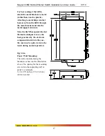
Page 22: ... into the metal support structure Since the 6KM has special internal thermal techniques to move the heat generated by the electronic components inside into the case the case may be quite warm to the touch during normal operation Fig 3 3 1a Panel Wall Mounting The unit is mounted using the brackets as shown in the illustration above The spacing for the mounting screws into the supporting wall or pa...

Page 23: ...t options are available to suit the 6KM Mobile Ethernet Switches to special high availability communications and or heavy industrial grade applications including 12VDC 48VDC 24VDC 110VDC 125VDC and 250VDC with single DC input 12VDC 48VDC 24VDC 110VDC 125VDC and 250VDC with dual DC input AC input with internal power supply see Section 1 2 for Ordering Information Fig 3 4a Single DC power input Powe...

Page 24: ...ggers an alarm in the user s monitoring system The second NC Alarm Contact is held closed when there is power on the main board inside of the Switch This provides a Hardware Alarm labeled H W because the NC contacts will open when internal power is lost either from an external power down condition or by the failure of the power supply inside of the Magnum Switch Useful info about Alarm contacts 1 ...

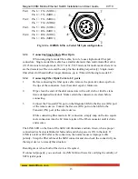
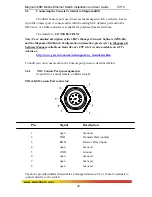
Page 25: ...um 6KM Switch Configuration information please refer to Magnum 6K Software Manual available on GarrettCom s FTP site It is also available on GCI s website at http www garrettcom com techsupport sw_downloads htm To build your own console cable the Console port pin out is described below 3 6 1 M12 Console Port pin assignments 8 pin M12 A coded female on 6KM switch M12 6KM Console Port connector Pin ...

Page 26: ...ed ports which must be configured through MNS software per unit as per the requirement The internal functions of both are described below Filtering and Forwarding Each time a packet arrives on one of the switched ports the decision is taken to either filter or to forward the packet Packets whose source and destination addresses are on the same port segment will be filtered constraining them to tha...

Page 27: ...the remote device Standard commercially available Fast Ethernet media converters mostly do not support auto negotiation properly and require that the switched port to which they are connected be at the 100Mb fixed speed Attachments to a 10 100 auto negotiation port typically will not work properly The 6KM Switch s M12 ports handle this situation by configuring the ports as per desired through MNS ...

Page 28: ...when data is moving from a 100Mb port to a 10 Mb port and the 10Mb port is unable to keep up It can also occur when multiple 100Mb ports are attempting to transmit to one 100Mb port and in other protracted heavy traffic situations Magnum 6KM Switches implement the 802 3x flow control non blocking on Full Duplex ports which provides for a PAUSE packet to be transmitted to the sender when the packet...

Page 29: ...e is 0 2 dB km ZX70 See http www garrettcom com techsupport power_budget pdf for more information on Power budget calculations 5 0 Magnum 6KM Mobile Ethernet Switch Port Modules This chapter describes each Port Module PM including appearance functionality and status displays 5 1 6KM Modules An important feature of the Magnum 6KM is the use of Port Modules for flexible mixed media connectivity to M...

Page 30: ...supplied to the unit M12 4 pin D coded 10 100Mb 1 LED per port Link A LED ON 10 100Mb LINK established BLINKING ACTIVITY M12 PoE 4 pin D coded 10 100Mb 1 LED per port ON PoE PoE device detected M12 8 pin A coded 1000Mb 2 Led per port ON 1000Mb LINK established top LED ON 10Mb LINK established bottom LED ON 100Mb LINK established both LED BLINKING ACTIVITY ...

Page 31: ... and User Guide 07 10 26 www GarrettCom com LC 100Mb Fiber port 2 LED per port L A LED ON LINK established BLINKING ACTIVITY F H LED ON Full Duplex OFF Half Duplex LC 1000Mb Fiber port 1 LED per port Link A LED ON LINK established BLINKING ACTIVITY ...

Page 32: ...e is a powered up device at the other end of the cable in order for a Link LED to provide valid indications of operating conditions on that port Using the 6K MNS 6K or MNS 6K SECURE management software the user may disable auto negotiation and fix the desired operation of each M12 port The user may select 10Mb or 100Mb speed and full or half duplex mode per port as per user requirements See Magnum...

Page 33: ...d properly to an IEEE 803 af compliant PD device on that port When non PoE devices are connected the PoE LED is OFF Operation of Ethernet data traffic is not affected by PoE PoE LEDs Summary For PoE devices each M12 PoE port supports only 802 3af complaint devices The PoE LED is ON when the attached PD is drawing power from the port The power is supplied on the data pairs per IEEE802 3af PoE stand...

Page 34: ...ber optic technology The cable end is a plug in connector with both fiber strands terminated in one housing that cannot be improperly inserted Each port has a Link Activity L A LED indicating proper connectivity Link with the remote device when lit and blinking Activity indicating packets being received and Full Half Duplex F H LED indicating Full Duplex ON and Half Duplex OFF 5 1 5 6KM4 4SLC 6KM4...

Page 35: ...gotiating and auto crossover MDIX for operation at 10 or 100Mb speed in full or half duplex mode i e each independently selects a mode and speed to match the device at the other end of the twisted pair cable Each port has a Link Activity L A LED indicating proper connectivity Link with the remote device when lit and blinking Activity indicating packets being received 5 1 7 6KM4 2SLC2RJ 6KM4 2SLCL2...

Page 36: ...able of distances up to 2km The 1000Mb Gigabit fiber port module on the Magnum 6KM are normally set factory default to operate at AUTO mode for best fiber distance and performance Each port has a Link Activity Link A LED indicating proper connectivity Link with the remote device when lit and blinking Activity indicating packets being received 5 1 10 6KM 2GSLC 6KM 2GSLCL 2 x Gigabit Singlemode LC S...

Page 37: ...e network are interoperable 2 Check the cables and connectors to ensure that they have been properly connected and the cables wires have not been crimped or in some way impaired during installation About 90 of network downtime can be attributed to wiring and connector problems 3 Make sure that power is properly attached to each Magnum 6KM Switch unit Use the PWR LEDs to verify each unit is receivi...

Page 38: ...s URL https rma garrettcom com rma rma_request_noaccount php to fill out the form Please have the following information readily available Name and phone number of your contact person Name of your company institution Your shipping address Product name Serial Number or Invoice Number Packing List Number or Sales Order Number Date of installation Failure symptoms including a full description of the p...

Page 39: ...t responsible for your return shipping charges 4 Ship the package to GarrettCom Inc 47823 Westinghouse Dr Fremont CA 94539 Attn Customer Service APPENDIX A WARRANTY INFORMATION GarrettCom Inc warrants its products to be free from defects in materials and workmanship for a period of three 3 years from the date of shipment by GarrettCom During this warranty period GarrettCom will repair or at its op...

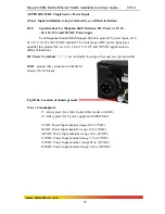
Page 40: ...product for use in 12 24 48 110 125 and 250VDC applications in different industries DC Power Terminals are internally floating so that user may ground either GND ground wire connection to the 6KM chassis 6 32 thread Fig B1 0a Location of chassis ground Power Consumption 15 watts typical for a fully loaded fiber model with 2Gb 10 watts typical for 8 ports copper and 100Mb fiber 12VDC Power Input no...

Page 41: ... This section describes the proper connection of the 12 24 48 110 125 and 250VDC to the DC power connector on the Magnum 6KM Switch The DC input connector on the Magnum 6KM Mobile Switch is located on the left front of the unit The power terminals are connected as shown below and they are electrically floating inside the unit so that either may be grounded by the user if desired The chassis is ear...

Page 42: ...2 Connect supply line to the unit 3 Apply power to the supply line 4 Confirm that the PWR led is illuminated B4 0 UL Requirements for DC powered units CAUTION 48VDC products shall be installed with a readily accessible disconnect device in the building installation supply circuit to the product Minimum 18AWG cable for connection to a Centralized DC power source 1 Minimum 14AWG cable for connection...

Page 43: ... to the hub chassis screw Input Two separate sources each at 36 60 VDC Power Supply Internal 110VDC Dual Source model Dual Src 110V DC Power Connector First Source A A 2nd Source B B GND ground wire connection to the hub chassis screw Input Two separate sources each at 77 137 VDC Power Supply Internal 125VDC Dual Source model Dual Src 125V DC Power Connector First Source A A 2nd Source B B GND gro...

Page 44: ... DC power sources are not mixed together by the hub c When one correct DC input is present the Switch will receive power if the other DC input is absent or even if it is connected with reverse polarity or shorted or grounded d Reverse polarity connections if they should accidentally occur on either input will not damage the Switch or power supply internally nor will it blow the fuse in the interna...

Page 45: ...cting live power lines to the input connector of 48VDC 12VDC 24VDC 110VDC 125VDC or 250VDC products always use a digital voltmeter to measure the output voltage of the power supply and determine the lead which is more ve potential The more ve voltage lead from 48V or 48V supply must be connected to the post labeled After confirmation of the output voltage 1 Turn off power to the supply line 2 Conn...

Page 46: ...47 to 63 Hz auto ranging The mating power cable connection to the 6KM switch is made utilizing a RD24 locking female connector Simply align the keyed female AC power cable connector to the 6KM male AC power input connector and twist the threaded lock to secure Recommended external power input connector not supplied with 6KM Manufacturer Binder USA Manufacturer pn 99 4222 00 04 Safety rating UL Rec...

Reviews: