GARO LS4 43kW Installation Manual Download Page 5

INSTALLATION

1.

Mount the LS4 and install the supply cable. See picture 
1-5.
Phase-rotation is recommended in order to achieve even 
load on all phases when several LS4 stations are installed 
to same mains. For example:
1st LS4: L1, L2, L3
2nd LS4: L3, L1, L2
3rd LS4: L2, L3, L1
And so on…. 
Note: When DLM is pre-configurated from factory, follow 
the marked phase order label at incoming terminals. All 
pre-configured LS4 contains the information about this 
inside the cabinet
The gasket at the bottom of the LS4 need to tighten 
properly around the mains cable in order to avoid dirt, 
dust, bugs etc to enter the LS4. See picture 4.
Note! The touch protection cover need to fix with 
attached screws to ensure proper earth bonding to 
the touch protection cover.

2.

In cases with LS4 stations connected in a grid, install TP 
cable CAT6 with RJ45 connectors between each LS4 
station and the provided ethernet router/switch (located 
ie. in the LS4 master. Se example of ethernet wiring 
diagram picture 6, 7.
In cases with LS4 stations connected in a grid, installation 
of the LS4 stations need to follow the installation order in 
the attached Master/slave file. See table 1.

3.

In cases with external energy meter (for DLM function), 
connect the energy meter communication terminals A- and 
B+ to LS4 Master station terminals 200 A-) and 201 
(B+). The energy-meters modbus adress must be set to 
#2. The modbus RS-485 communication settings is: Baud 
9600, 8bit, 1 stop bit, no parity

4.

Turn on the electric power.

5.

Test the LS4 station on both sides with a EVSE-tester or an 
EV. In cases where authorization (by RFID tag or similar)  
is needed to start charging please contact the backend 
administrator.

6.

Fill in the warranty form completely.

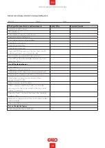
Example of Master/Slave form for LS4 stations connected in a grid

Role

Serialnumber / M-number

Master

M00001

Slave 1

M00002

Slave 2

M00003

Slave 3

M00004

Slave 4

M00005

Slave 5
Slave 6
Slave 7
Slave 8
Slave 9
Slave 10

INSTALLATION

5

EN

Summary of Contents for LS4 43kW

Page 1: ...GARO LS4 43kW Installation Manual EN GARO AB Box 203 SE 335 25 Gnosj Phone 46 0 370 33 28 00 info garo se garo se Manual 380316 1 0 EN...

Page 2: ...utions 4 General Information 4 Content 4 INSTALLATION 5 NORMAL USE 9 Electrical diagram 14 Technical specifications 17 Service information 17 Form for annual service and maintenance 18 Warranty Condit...

Page 3: ...FETY INFORMATION The LS4 stations are designed exclusively for charging electric vehicles All installation must be carried out by an authorized installer and comply with local country installation reg...

Page 4: ...er behind the front door When contacting GARO support please have the M number available LS4 stations that are pre configurated for backend solution have the ChargeBoxID CBID labeled under the M numbe...

Page 5: ...the provided ethernet router switch located ie in the LS4 master Se example of ethernet wiring diagram picture 6 7 In cases with LS4 stations connected in a grid installation of the LS4 stations need...

Page 6: ...picture 1 picture 2 Cu 2 5Nm Al 4Nm OPTION INSTALLATION CU AL 6 EN...

Page 7: ...0 8Nm 0 05 picture 3 picture 4 picture 5 INSTALLATION 7 EN...

Page 8: ...P CAT6 cable to router switch 5pcs LS4 connected with TP CAT6 cable to router switch picture 6 picture 7 Example of DLM meter installation Modbus address 2 9600 8 1 no parity Terminals 200 A 201 B DLM...

Page 9: ...ing station have received command from backend to start charging and is waiting for car to connect Firm Car connected Charging is ongoing state C Car connected Charging is paused state B Blinking When...

Page 10: ...g without success Contact installer or GARO Support please have M number available Check car settings that can influence charging i e gear in parking mode doors closed car locked etc Present a valid R...

Page 11: ...kend charger configuration OperatorCurrentLimit Check motor locking wiring and connection for damages Verify that locking mechanism rod and arm are not stuck Verify that the connector is properly inse...

Page 12: ...black cables were disconnected then it has deteced an earth fault in one of the DC powered components controllers upper PCB router switch etc inside the charging station If LED light DC OK remains tu...

Page 13: ...Vehicle not connected Firm CHARGING occupied C Vehicle connected ready CHARGING suspendedEV B Vehicle connected not ready Blinking Reserved Firm RCD triggered groundFailure Residual current detected...

Page 14: ...XN1 Neutral Terminal Block QA1 Contactor XPE1 Protection Earth Terminal Block 1 XPE2 Protection Earth Terminal Block 2 CT1 Current transformer 100A CT2 Current transformer 100A CT3 Current transforme...

Page 15: ...CT3 XPE2 XPE1 P1 CC1 A MOD CC1 B MOD AC Terminal 35 Feritte 525 Ohm DOUBLE INSULATED CABLE 16 1 5 XN1 L N EB1 Heater Cold Option 10A FC3 I 2 1 P1 11 P1 11 XD1 CP 201 200 External Energy Meter A1 A2 Q...

Page 16: ...o t o M Motor HS1 Relais 13 Motor HS2 Relais 14 GND2 Modbus B2 Modbus A2 Modbus WA Relais 23 WA Relais 24 RJ45 CC1 Down Side 0V 12V DC Terminal A1 A2 K3 OUT IN OUT IN CC RFID 12V GND HEAT Top Card KF1...

Page 17: ...ID output power 250mW SERVICE INFORMATION Care and maintenance GARO charging station LS4 The warranty will only remain valid if service is performed Service is performed once a year and must be docume...

Page 18: ...cation by 2 or 3 flashes from LED s Turn off the electrical power Check gaskets Check torque for mains terminals Check torque for LS4 fixing screws towards ground wall Check torque on standard compone...

Page 19: ...l number 7 Warranty does not cover damage occurred by incorrect use of equipment use of any non original spare parts lack of maintenance or faults caused by disassembly of the product or unauthorized...

Page 20: ...ANTIFORMUL R LS4 Model M no Electrical installation data Group fuse A Supply cable dimension Function Test Testbox EV model Date Sign Installer Company Name Owner Customer Name Installation adress WAR...

Page 21: ...DECLARATION OF CONFORMITY 21 EN...

Page 22: ...GARO AB Box 203 SE 335 25 Gnosj Phone 46 0 370 33 28 00 info garo se garo se EN...

Reviews: