background image

2-13

190-01007-03  Rev. B

Garmin GTN 725/750 Pilot’s Guide

Foreword

Getting 

Started

Audio &  

Xpdr Ctrl

Com/Nav

FPL

Direct-To

Proc

Charts

Wpt Info

Map

Traffic

Terrain

Weather

Nearest

Music

Utilities

System

Messages

Symbols

Appendix

Index

2.2.9 

Playback Controls

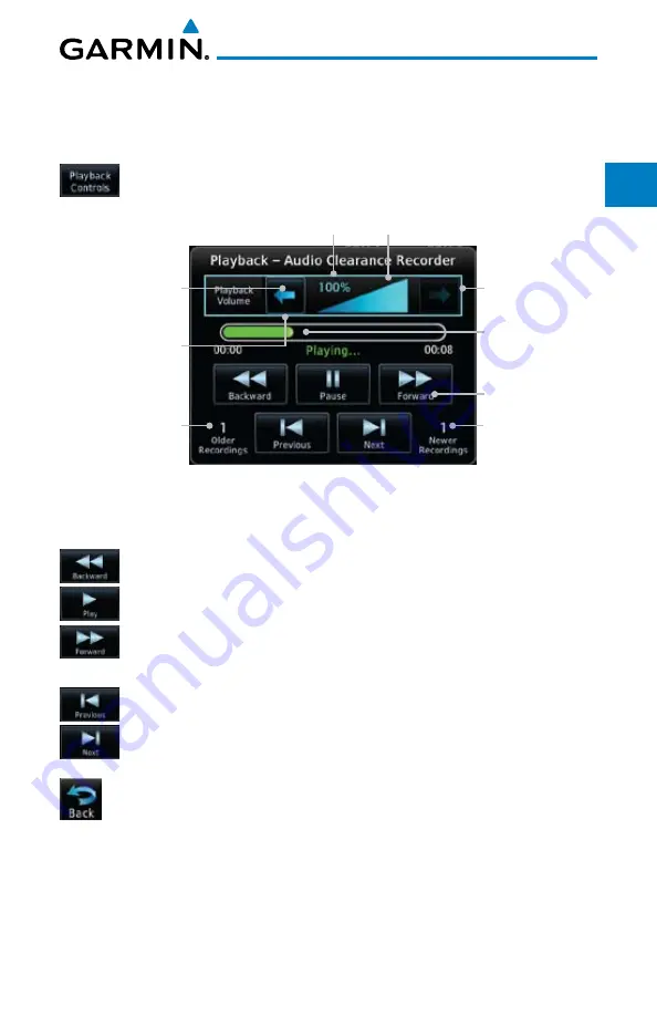
The voice recorder feature records all the audio heard on any selected COM 

radio. Playback is heard by anyone listening on the selected radios. 


1.  While the Audio Control page is displayed, touch the 

Playback 

Controls

 key to display the Playback Control selections. 

Recording Time 

Line

Playback Controls
Number Of 

Recordings Made 

After The Current  

Selection

Number Of 

Recordings 

Made Before 

The Current  

Selection

Touch To 

Increase Volume

Touch To 

Decrease Volume

Percent Of Maximum Volume

Graphic Scale Showing Volume

Heavy Outline 

Indicates The Upper 

Left Rotary Knob 

Controls Volume

Figure 2-16  Audio Panel Playback Controls


2.  Touch the 

Playback Volume

 arrows to set the volume. 


3.  Touch the 

Backward

Play

, or 

Forward

 keys to control the 

playback of the currently selected recording. 


4.  Touch the 

Previous

 or 

Next

 keys to select a recording. 


5.  Touch the 

Back

 key to return to the Audio Panel page. 

Summary of Contents for GTN 750

Page 1: ...Map Traffic Terrain Weather Procedures Charts Waypoint Info Nearest System Music Utilities GTN 725 750 Pilot s Guide Flight Plan...

Page 2: ...sseminated downloaded or stored in any storage medium for any purpose without the express written permission of Garmin Garmin hereby grants permission to download a single copy of this manual and of a...

Page 3: ...R EXPRESS IMPLIED OR STATUTORY INCLUDING ANY LIABILITY ARISING UNDER ANY WARRANTY OF MERCHANTABILITY OR FITNESS FOR A PARTICULAR PURPOSE STATUTORY OR OTHERWISE THIS WARRANTY GIVES YOU SPECIFIC LEGAL R...

Page 4: ...a very high degree of functional integrity However the pilot must recognize that providing monitoring and or self test capability for all conceivable system failures is not practical Although unlikel...

Page 5: ...the risk of unsafe operation carefully review and understand all aspects of the GTN 725 750 Pilot s Guide Thoroughly practice basic operation prior to actual use During flight operations carefully com...

Page 6: ...ources and contact your Flight Service Station for interpretation of TFR data NOTE All visual depictions contained within this document including screen images of the GTN bezel and displays are subjec...

Page 7: ...tion To obtain accessories for your unit please contact your Garmin dealer Help us better support you by completing our on line registration form today Registration ensures that you will be notified o...

Page 8: ...d Audio Xpdr Ctrl Com Nav FPL Direct To Proc Charts Wpt Info Map Traffic Terrain Weather Nearest Music Utilities System Messages Symbols Appendix Index Record of Revisions Part Number Revision Date De...

Page 9: ...re Data Card 1 3 1 3 2 Pilot Controls 1 4 1 3 2 1 Volume Squelch Knob 1 4 1 3 2 2 Large Small Concentric Knobs 1 4 1 3 2 3 HOME Key 1 5 1 3 2 4 Direct To Key 1 5 1 3 2 5 Touchscreen Keys 1 5 1 4 Unit...

Page 10: ...Audio Panel Operation 2 6 2 2 1 Mic Selection 2 8 2 2 1 1 Mic Window Mic Selection 2 8 2 2 1 2 Audio Panel Page Mic Selection 2 8 2 2 2 Monitor 2 9 2 2 3 Passenger Address 2 9 2 2 4 Cabin Speaker Sel...

Page 11: ...Creating a New Flight Plan in the Catalog 4 2 4 1 2 Creating a New Flight Plan from the Active Flight Plan 4 3 4 2 Active Flight Plan Page 4 4 4 2 1 Waypoint Options 4 5 4 2 1 1 Activate Leg 4 6 4 2...

Page 12: ...rse 5 8 6 Procedures 6 1 6 1 Basic Approach Operations 6 2 6 2 Selecting a Departure 6 4 6 3 Selecting an Arrival 6 7 6 4 Selecting an Approach 6 10 6 5 Approaches with Procedure Turns 6 13 6 6 Flying...

Page 13: ...sing SafeTaxi 7 16 7 5 2 Hot Spot Information 7 17 7 5 3 SafeTaxi Cycle Number and Revision 7 17 8 Waypoint Info 8 1 8 1 Waypoint Selection 8 3 8 2 Airport 8 4 8 2 1 Info 8 4 8 2 2 Preview 8 5 8 2 3 P...

Page 14: ...er Optional 9 21 9 1 3 Map Data Fields 9 21 9 1 4 Map Detail 9 23 9 2 Map Panning 9 25 9 3 Map Controls 9 28 9 3 1 Pan Map Mode 9 28 9 3 2 Create Waypoint 9 28 9 3 3 Graphically Edit Flight Plan Mode...

Page 15: ...rrain Page 120 Arc or 360 Rings 11 4 11 2 2 Terrain Limitations 11 5 11 3 Terrain Awareness and Warning System TAWS B Optional 11 6 11 3 1 TAWS B Requirements 11 6 11 3 2 TAWS B Limitations 11 6 11 3...

Page 16: ...Movement 12 15 12 1 9 SIGMETs and AIRMETs 12 16 12 1 10 County Warnings 12 17 12 1 11 Freezing Level 12 18 12 1 12 METARs 12 19 12 1 13 Cyclone 12 20 12 1 14 Lightning 12 21 12 1 15 Weather Forecast 1...

Page 17: ...Preset 14 7 14 2 4 2 Recalling a Preset 14 7 14 3 GDL 69 69A Data Link Receiver Troubleshooting 14 8 15 Utilities 15 1 15 1 Vertical Calculator VCALC 15 3 15 1 1 Target Altitude 15 5 15 1 2 Altitude T...

Page 18: ...Nearest Airport Criteria 16 16 16 4 1 4 Crossfill 16 18 16 4 1 5 CDI Scale Selection 16 19 16 5 Alerts Settings 16 20 16 6 Units Settings 16 22 16 6 1 Setup Units 16 22 16 6 2 Setting a User Configure...

Page 19: ...network of Garmin Aviation Distributors About This Guide Take a little time to review the various sections of this guide to familiarize yourself with it First read Section 1 as an introduction to quic...

Page 20: ...used will be shown to the left of a procedure Keys are outlined areas on the display Figures in the guide will identify the available controls A key may have a name of a control such as Enter Terrain...

Page 21: ...panel space The GTN 725 and 750 have their own GPS SBAS navigator and flight planning functions The GTN 750 adds VHF Com and VHF Nav radios Selected optional external equipment allows you to display...

Page 22: ...Conventions Bold text indicates a control The small right knob is the smaller inner knob of the two concentric rotary knobs on the lower right corner of the bezel The large right knob is the larger ou...

Page 23: ...lay providing information as well as a touchscreen controls The GTN 7XX has a 800 x 600 pixel 6 9 inch LCD display Large and Small Knobs Volume Squelch On Off and Nav ID On Off Active Com Frequency St...

Page 24: ...e located on the bezel and on the touchscreen display Controls are comprised of dual concentric knobs volume squelch knob bezel keys and active touch areas on the display 1 3 2 1 Volume Squelch Knob T...

Page 25: ...e Map page from any other page Figure 1 5 HOME Key Touch The Key To Access The Function Page Or Function Name Figure 1 6 Home Page 1 3 2 4 Direct To Key The Direct To key provides access to the direct...

Page 26: ...Start Up Screens During system initialization test annunciations are displayed All system annunciations should disappear typically within the first 30 seconds after power up Upon power up key annuncia...

Page 27: ...gs 1 When the System and Database Version page appears check to ensure databases are current Then touch Continue Check To Ensure Required Databases Are Present And Current Touch To Continue To Home Pa...

Page 28: ...te values as desired Fuel capacity is shown in either gallons or pounds as set in the Units feature of System mode Touch To Set Current Fuel Quantity Start Up Instrument Panel Test Conditions Touch To...

Page 29: ...ouch To Accept Fuel on Board Values Touch To Display Fuel Tabs Capacity Selected Fuel on Board Capacity Touch Keys To Select Fuel Capacity Values Figure 1 12 Fuel On Board Page 5 Touch the Set Full Ta...

Page 30: ...eypad to set those values Touch the Enter key after selecting the Fuel Flow values Touch To Delete Characters Touch To Accept Fuel Flow Values Selected Fuel Flow Value Touch Keys To Select Fuel Flow V...

Page 31: ...pt for the knobs the HOME and Direct To keys on the bezel the controls for the GTN 7XX are located on the display and activated by your touch Back to Previous Page Touchscreen Keys Touch to Toggle Act...

Page 32: ...s 1 From the Home page touch System and then Setup 2 Select the desired Time Format and Local Offset by touching the Time Format 12 Hour 24 Hour and or UTC keys and selecting the appropriate Local Tim...

Page 33: ...tem key and select the desired value 3 Continue to select the desired Units values and then touch the Back or HOME key to exit 1 5 2 3 Alerts Settings Values 1 From the Home page touch System and then...

Page 34: ...Waypoints Flight Plan Catalog Alerts traffic popup acknowledgement missed approach waypoint popup acknowledgement altitude leg popup acknowledgement External sensors transponder status and commands s...

Page 35: ...ypoint Identifier field and select the characters for the desired waypoint with the large and small right knobs or the touch keypad OR 3 Touch Activate or press the small right knob Text near the smal...

Page 36: ...ning control normally remains in the Com window and will return after 30 seconds of inactivity If you wish to select a VOR localizer ILS frequency press the small right knob momentarily to make the Na...

Page 37: ...ncy 1 Touch the Active top frequency window Active Com Frequency Touch to Flip Flop Standby Com Frequency Figure 1 19 Com Radio Frequency Windows Touch Active to Flip Flop 2 Each touch of the Active w...

Page 38: ...Departures SIDs arrivals STARs non precision and precision approaches are available using the PROC Procedures key Select an Approach 1 Touch the PROC key on the Home page 2 Touch the Approach key and...

Page 39: ...ble and the unit is in Dead Reckoning mode All external outputs dependent on GPS position are flagged Terrain will be noted as not available and new terrain advisory pop ups will not occur Traffic and...

Page 40: ...uide 190 01007 03 Rev B Foreword Getting Started Audio Xpdr Ctrl Com Nav FPL Direct To Proc Charts Wpt Info Map Traffic Terrain Weather Nearest Music Utilities System Messages Symbols Appendix Index T...

Page 41: ...ponder such as one of the GTX family of transponders functions See your dealer for more information 2 1 Transponder Operation The GTN 7XX will operate as a control head for remotely connected optional...

Page 42: ...gh the available transponders Active Transponder Figure 2 3 Active Transponder Indication 2 The active transponder will be shown on the key 2 1 2 IDENT 1 Touch the IDENT key once to reply with an iden...

Page 43: ...e Figure 2 5 Transponder Mode Ground Indication 2 1 5 On 1 Touch the On key for Mode A operation The transponder is On and will transmit its squawk code when interrogated Transponder Operation ON Mode...

Page 44: ...k code the original code will be used until you are finished selecting the new code Squawk Code Description 1200 Default VFR code in the USA 7500 Hijacking 7600 Loss of Communications 7700 Emergency T...

Page 45: ...er Nearest Music Utilities System Messages Symbols Appendix Index 3 Touch the numeric keypad or use the rotary knobs to select the desired Squawk Code Squawk Code Character Selected For Editing Figure...

Page 46: ...ll operate as a control head for remotely connected optional compatible audio and intercom equipment such as the Garmin GMA 35 Intercom Setup Monitor and Mic Selections Audio Panel Controls Touch To D...

Page 47: ...2 Com 3 Nav 1 Nav 2 DME ADF MIC Selection Com 1 Com 2 Com 3 Passenger Address Mic 1 2 3 Mon 1 2 3 Audio Panel Split Mode Cabin Speaker Split Mode Playback Controls Cabin Speaker Speaker Volume Marker...

Page 48: ...the Mic window to toggle between Mic 1 and Mic 2 2 Note that the selected Mic is automatically monitored 3 If Mic 3 or Passenger Address PA are selected touching the Mic window will revert to toggling...

Page 49: ...hich radios are being listened to 1 Monitor is automatically selected for the associated Com Mic Radio 1 2 or 3 For example when Com 1 is selected Mon 1 is automatically active 2 Touch the Mon key to...

Page 50: ...Audio When Marker is selected green bar shown the tones for Marker Beacons are heard When Marker is not selected green bar not shown the tones for Marker Beacons are not heard The GMA 35 marker beaco...

Page 51: ...14 Audio Panel Marker Beacon Tone Volume Selection 2 2 6 Marker Hi Sense The Marker Hi Sense setting allows detecting the outer Marker Beacon from a greater distance 1 While theAudio Control page is d...

Page 52: ...n the Split mode the pilot and co pilot may talk and listen independently to the radios or PA as selected Crew Intercom Activation Select Audio Split Mode Touch And Drag Finger To Scroll List of Radio...

Page 53: ...y to display the Playback Control selections Recording Time Line Playback Controls Number Of Recordings Made After The Current Selection Number Of Recordings Made Before The Current Selection Touch To...

Page 54: ...pped with a PTT key 1 Touch the Intercom window at the top of the display to display the Intercom Setup page Touch Source To Configure Touch To Display Intercom Setup Touch To Configure Co Pilot Volum...

Page 55: ...elected radios pilot co pilot Selected radios co pilot pilot passengers Co pilot passengers Selected radios pilot passengers Selected radios co pilot Pilot passengers Selected radios pilot Selected ra...

Page 56: ...er Nearest Music Utilities System Messages Symbols Appendix Index Intercom Setup Pilot VOL SQ Volume Squelch Co Pilot VOL SQ Volume Squelch Music 1 Music 2 Music Distribution Pilot Co Pilot Passenger...

Page 57: ...Passenger VOL SQ keys to set the Volume and Squelch for the selected item Touch To Select Manual Or Auto Squelch Touch To Increase Volume Touch To Decrease Volume Heavy Outline Indicates The Upper Le...

Page 58: ...configuration Touch To Select Music Recipients Touch To Select Source That Will Mute Music Percent Of Maximum Volume Graphic Scale Showing Volume Touch To Increase Volume Touch To Decrease Volume Hea...

Page 59: ...s to talk at once The TEL channel may be disabled in Configuration mode Contact a Garmin authorized service center for details 1 While viewing the Intercom Setup page touch the Telephone key to set it...

Page 60: ...uide 190 01007 03 Rev B Foreword Getting Started Audio Xpdr Ctrl Com Nav FPL Direct To Proc Charts Wpt Info Map Traffic Terrain Weather Nearest Music Utilities System Messages Symbols Appendix Index T...

Page 61: ...ce band from 118 000 to 136 975 MHz in 25 kHz steps default For European operations a Com radio configuration of 8 33 kHz steps is also available Large and Small Knobs Frequency Adjust Volume and Sque...

Page 62: ...econds after releasing the Volume knob 3 2 Squelch The Com radio features an automatic squelch to reject many localized noise sources You may override the squelch function by pressing the Volume knob...

Page 63: ...d in the standby field it may be transferred to the active frequency by touching the active frequency field NOTE The Com window is normally active for adjustment unless the NAV window is made active b...

Page 64: ...Editing Window Frequency Monitor Annunciation Backspace Frequency Clear Key Frequency Monitor Key Frequency Transfer Flip Flop Key Find Frequency Key Enter Key Numeric Keypad Figure 3 5 Com Standby Fr...

Page 65: ...uencies from some of the main GPS pages To select a Com frequency for a User created frequency Recent selected frequency Nearest airport or from your Flight Plan 1 While viewing the numeric keypad tou...

Page 66: ...tly selected frequencies will be displayed Selected Frequency Category Touch Frequency From Recent List To Select Standby Frequency Recent Frequency Category Figure 3 7 Recent Com Frequency List 2 Tou...

Page 67: ...ymbols Appendix Index 2 Touch the Multiple FREQ key to show the available frequencies Touch A Frequency Key To Place It In The Standby Window Figure 3 9 Nearest Airport Multiple Frequency List 3 Touch...

Page 68: ...ndix Index 5 Some frequencies will have more information detail available Touch the key that shows More Information Touch For More Information Figure 3 11 More Information Is Available For Some Freque...

Page 69: ...t For Nearest Airport Selected Frequency Category Selected Frequency Category Figure 3 13 Flight Plan Frequency List 2 Touch the Multiple FREQ key to show the available frequencies if present 3 Touch...

Page 70: ...her Nearest Music Utilities System Messages Symbols Appendix Index Add User Frequency User Frequency Selection Figure 3 14 Add New User Frequency 3 The Add New User Frequency information window will n...

Page 71: ...e characters from the alphanumeric keypad for the desired name Touch the Enter key to accept the displayed Name User Frequency Name Alphanumeric Keypad Backspace Cursor Movement Figure 3 16 Select a N...

Page 72: ...cursor status or loss of the display To quickly tune and activate 121 50 press and hold volume knob or the remote Com flip flop key for approximately two seconds If the external remote key is used fur...

Page 73: ...ote recall switch will load the next preset Com frequency into the unit s Standby frequency box The remote recall switch can be pressed multiple times to scroll the entire preset frequency list throug...

Page 74: ...small MON annunciation is displayed to the right of the Standby frequency A green bar will show on the Monitor key When the Active frequency receives a signal the unit will switch automatically to th...

Page 75: ...Text Active Nav Frequency Standby Nav Frequency Touch To Flip Flop NAV STBY Touch To Edit STBY Figure 3 20 Nav Frequency Window 3 5 1 Ident Audio and Volume Nav ident is enabled by pressing the Volume...

Page 76: ...Com window unless placed in the Nav window by pressing the small right knob When the tuning cursor is in the Nav window it automatically returns to the Com window after 30 seconds of inactivity The a...

Page 77: ...d frequency Recent selected frequency Nearest airport or from your Flight Plan 1 While viewing the numeric keypad touch the Find key at the bottom of the display Categories for User Recent Nearest and...

Page 78: ...Ctrl Com Nav FPL Direct To Proc Charts Wpt Info Map Traffic Terrain Weather Nearest Music Utilities System Messages Symbols Appendix Index OR 4 Touch the Filter key to narrow the list by category such...

Page 79: ...irway is shown for waypoints on a published airway Figure 4 1 Flight Plan Functional Diagram NOTE The Chart feature provides a digital representation of a paper chart and provides no vertical or later...

Page 80: ...g a New Flight Plan in the Catalog 1 From the Home page touch Flight Plan 2 Touch Menu and then the Catalog key 3 Touch the Create New Catalog Route key at the end of the flight plan list in the Catal...

Page 81: ...Flight Plan touch Menu and then the Delete and OK keys to delete the existing active flight plan The stored flight plan in the Catalog will not be deleted 3 Touch the AddWaypoint key and select a way...

Page 82: ...ws each waypoint for the flight plan along with the Desired Track DTK Distance DIST for each leg and Cumulative Distance CUM The data fields are user selectable and may be changed to display Cumulativ...

Page 83: ...Symbols Appendix Index 4 2 1 Waypoint Options 1 While viewing the Active Flight Plan page touch the desired flight plan waypoint The Waypoint Options window will be shown Touch Key To Select Option W...

Page 84: ...eWaypoint Options menu touch the desiredTO waypoint and then the Activate Leg key to select the TO waypoint as the active leg for navigation Touch to Select As New TO Wpt and To Activate Leg Current L...

Page 85: ...the Active Flight Plan page touch the desired waypoint in the flight plan The Waypoint Options list will be displayed Insert Before Option Was Selected Option Will Insert New Waypoint Before This Sele...

Page 86: ...m Messages Symbols Appendix Index 4 Then touch Enter to confirm the selection or touch Cancel to cancel any changes The new flight plan will be shown New Waypoint Inserted Before The Selected Flight P...

Page 87: ...after the selected waypoint 3 Select a waypoint identifier with the alphanumeric keypad Then touch Enter to confirm the selection or touch the Cancel key to cancel the operation and return to theWayp...

Page 88: ...ection from the Waypoint Options will start the Procedures function See the Procedures section for complete information 1 On the Active Flight Plan page touch the desired waypoint in the flight plan T...

Page 89: ...function See the Waypoint Info section for complete information 1 On the Active Flight Plan page touch the desired waypoint in the flight plan The Waypoint Options list will be displayed 2 One Waypoin...

Page 90: ...as legs in flight plans with any waypoint that is part of an airway such as a VOR 1 On the Active Flight Plan page touch the desired VOR entry waypoint in the flight plan TheWaypoint Options list wil...

Page 91: ...c Terrain Weather Nearest Music Utilities System Messages Symbols Appendix Index 3 Touch the desired airway to select it Touch To Insert Selected Airway Figure 4 18 Select an Airway from the List 4 Sc...

Page 92: ...r finger to view the airway detail If changes are desired touch the Airway or Exit Waypoint keys to select alternate choices Touch To Select Exit Waypoint Touch To Load Airway Into FPL Airway Waypoint...

Page 93: ...Airway Options Make the desired choice or touch Back Touch To Collapse Airway Waypoints Touch To Select New or Change Current Airway Touch To Remove Airway From Flight Plan Airway Detail Shown Figure...

Page 94: ...s View Catalog Store Flight Plan Delete Flight Plan Preview Flight Plan Parallel Track Invert Flight Plan and Edit Data Fields Touch To Invert The Active Flight Plan Touch To Store The Active Flight P...

Page 95: ...to store the currentActive Flight Plan into the Catalog The flight plan will be named by the beginning and ending waypoints 3 When a duplicate flight plan is created the Store key will not be availabl...

Page 96: ...track line will be drawn offset from the original by the selected distance The original course line will be drawn in grey The aircraft will navigate to the parallel track course line and external CDI...

Page 97: ...ed parallel track offset and distance to determine whether that flight plan combined with the offset and distance support parallel track 1 While viewing the Flight Plan page touch the Menu key and the...

Page 98: ...ymbols Appendix Index PTK Active Symbol Active FPL Leg Figure 4 29 Parallel Track Shown in the Active Flight Plan Page 5 To deactivate Parallel Track while viewing the Active Flight Plan touch the Men...

Page 99: ...e data fields are user selectable and may be changed to display Cumulative Distance CUM Distance DIS Desired Track DTK En Route Safe Altitude ESA Estimated Time of Arrival ETA or Estimated Time En rou...

Page 100: ...rest Music Utilities System Messages Symbols Appendix Index 2 Touch one of the field keys to select from the list Selected Field Type Figure 4 33 Flight Plan Data Fields List 3 Touch the Up or Down ke...

Page 101: ...y the Departure and Destination waypoint Any timeyouactivateaflightplan acopyoftheflightplanisautomaticallytransferred to Active Flight Plan page and overwrites any previously active flight plan 1 Whi...

Page 102: ...d flight plan to select it The Route Options menu will be displayed 2 Touch the Activate key and then touch OK The selected flight plan will be activated Figure 4 36 Touch OK to Replace the Existing A...

Page 103: ...view key A map view of the flight plan and list of the waypoints will be displayed 3 Touch the Back key to return to the Flight Plan Catalog 4 3 5 4 Catalog Route Option Edit 1 While viewing the Fligh...

Page 104: ...flight plan to select it The Route Options menu will be displayed 2 Touch the Copy key You will be prompted to copy the selected flight plan Figure 4 39 Flight Plan Catalog Route Copy Option 3 A copy...

Page 105: ...usic Utilities System Messages Symbols Appendix Index 4 3 5 6 Catalog Route Option Delete 1 While viewing the Flight Plan Catalog page touch the desired flight plan to select it The Route Options menu...

Page 106: ...ive Flight Plan using the Delete Flight Plan key on the Flight Plan menu clears the waypoints from the Active Flight Plan but does not remove the flight plan from the Catalog 4 3 6 1 Delete Flight Pla...

Page 107: ...earest Music Utilities System Messages Symbols Appendix Index 4 3 6 2 Delete Active Flight Plan 1 While viewing the Active Flight Plan page touch the Menu key and then the Delete Flight Plan key Figur...

Page 108: ...n 1 While viewing the Flight Plan page touch the Menu key and then the Preview key A preview of the Active Flight Plan will be shown Map View of Flight Plan Legs Flight Plan Waypoint List Current Owns...

Page 109: ...n conjunction with the GTN 7XX Direct To function to quickly set a course to a nearby facility 5 1 Direct To Navigation 1 Press the Direct To key on the right side of the unit A flight plan must be ac...

Page 110: ...e numeric keypad to select the course and then touch the Enter key Numeric Keypad Selected Course Backspace Key Figure 5 2 Direct To Course Selection 5 Touch the desired waypoint and touch the Activat...

Page 111: ...ght side of the unit 2 Touch the FPL tab at the top of the Direct To window Touch Waypoint Key To Select Flight Plan Waypoint List Flight Plan Tab Figure 5 4 Direct To Flight Plan Leg Selection 3 Touc...

Page 112: ...ill now be displayed with the new Direct To course 5 3 Direct To a Nearest Airport 1 Press the Direct To key on the lower right side of the unit 2 Touch the NRST APT tab at the top of the Direct To wi...

Page 113: ...lities System Messages Symbols Appendix Index 3 Touch the desired airport to select it The selected airport will be displayed in the Waypoint page Activate Direct To Course Direct To Waypoint Figure 5...

Page 114: ...the previously active flight plan will be reactivated and the nearest leg to the aircraft position will become the active leg If there was no active flight plan after cancelling the Direct To course t...

Page 115: ...aving an existing location name will create a waypoint with the name MAPWPT Touching the Direct To key will automatically insert the selected waypoint as the Direct To waypoint The MAPWPT will be save...

Page 116: ...ute Direct To course may be selected by using the Waypoint tab Nrst Apt tab or selecting an airport on the map When an off route Direct To course is activated the existing active flight plan will be d...

Page 117: ...Selections are also shown to Activate Approach Vectors to Final and Activate Missed Approach NOTE The Chart feature provides a digital representation of a paper chart and provides no vertical or late...

Page 118: ...ion approaches have GPS overlays to let you fly an existing procedure VOR VOR DME NDB etc more accurately using GPS Many overlay approaches are more complex in comparison to GPS only approaches The GT...

Page 119: ...nimums LNAV V GPS approach using published LNAV minima Advisory vertical guidance is provided Fly to LNAV minimums LNAV Lateral Navigation approach Fly to LNAV minimums MAPR Missed Approach indicates...

Page 120: ...hen another departure is already in the active flight plan the new departure replaces the previous departure The route is defined by selection of a departure the transition waypoint and a runway NOTE...

Page 121: ...arture Transition Figure 6 3 Selecting a Transition for a Departure 4 Touch the key for the desired Runway if necessary The Departure page with preview will be displayed Touch To Select Runway Touch T...

Page 122: ...ex 5 Touch the Load Departure key The Active Flight Plan page will be displayed Scroll To View Flight Plan With Departure Waypoints Touch To Edit Waypoint Touch To Change Or Remove Departure Figure 6...

Page 123: ...at a time in a flight plan If an arrival is loaded when another arrival is already in the active flight plan the new arrival replaces the previous arrival The route is defined by selection of an arri...

Page 124: ...ect Desired Arrival Transition Figure 6 9 Select Transition 4 Touch the key for the desired Runway if necessary NOTE If the selected runway is depicted as RW10B for instance this means both runways 10...

Page 125: ...s Wpt Info Map Traffic Terrain Weather Nearest Music Utilities System Messages Symbols Appendix Index 6 Touch the Load Arrival key The Active Flight Plan page will be displayed Scroll To View Flight P...

Page 126: ...an the new approach replaces the previous approach The route is defined by selection of an approach the transition waypoint and a runway 1 Touch the PROC key on the Home page The Approach Arrival and...

Page 127: ...the key for the desired approach Figure 6 13 Selecting an Approach 4 After selecting the approach for the destination airport the approach options will be displayed Final Approach Fix Missed Approach...

Page 128: ...l and ID are typically loaded automatically if they are present NOTE As an alternate means of loading an approach the Channel ID key allows you to select the channel ID for a SBAS approach for the cur...

Page 129: ...so activate the selected procedure on the Procedures page if the approach is not activated on this page Destination Airport Approach Waypoints Direct To Waypoint Phase of flight Sequencing Suspended F...

Page 130: ...eached a pop up will appear Figure 6 18 Pop Up Upon Reaching the MAP 2 Touch the Remain Suspended key to continue with sequencing suspended or touch Activate GPS Missed Approach for guidance to the Mi...

Page 131: ...Approach Approaches that contain DME arcs are supported by the GTN The GTN will provide guidance left right relative to the arc If you wish to activate the DME arc leg manually the aircraft must be ne...

Page 132: ...VLOC GPS GPS Auto Switch to VLOC within this area The GTN 7XX can be set to automatically switch the external CDI output from GPS to VLOC as you intercept the final approach course if used with a KAP...

Page 133: ...approaches according to the published chart Phase of flight Annunciation Description Minimums L VNAV Lateral Navigation Vertical Navigation RNAV non precision approach with advisory vertical guidance...

Page 134: ...e legs For roll steering autopilots roll steering is terminated when approach mode is selected on the autopilot and is available once the missed approach is initiated If Vectors to Final is activated...

Page 135: ...enoughtimetorespondandintercepttheapproach course prior to the FAF depending upon the performance characteristics of your autopilot and aircraft In such instances you should manually fly the approach...

Page 136: ...KFC225 Autopilot outputs for the King KAP140 KFC225 autopilots are activated manually by the pilot after being prompted during the approach procedure After enabling outputs the GTN 7XX will provide g...

Page 137: ...e Flight Plan or Procedures portion of the system The absence of a particular Departure Arrival or Approach under the Flight Plan or Procedures portion of the system does not preclude the ability to v...

Page 138: ...he Chart page is displayed 1 The most recently selected chart during the current power cycle if valid 2 The airport surface chart for the nearest airport if on ground and nearest airport is found 3 Th...

Page 139: ...rt Information Chart Touch to View Airport Approach Departure Arrival Charts Touch To Change Chart Scale Touch For Full Display View Of Chart Touch to Select Airport Info Chart Touch to View Airport W...

Page 140: ...dex 7 1 2 Info 1 Touch the Info key to select the specific information chart Touch To View Selected Airport Info Figure 7 4 Airport Info Selection 2 Touch an item from the list to view the chart Touch...

Page 141: ...ages Symbols Appendix Index 7 1 4 Approaches 1 Touch the Approaches key to view available approaches Touch To View Approach List Selected Airport Detailed View Of Selected Approach Touch To View Appro...

Page 142: ...Messages Symbols Appendix Index 7 1 5 Departures 1 Touch the Departures key to view available departures Touch To View Departure List Selected Airport Detailed View Of Selected Departure Figure 7 8 De...

Page 143: ...Symbols Appendix Index 7 1 6 Arrivals 1 Touch the Arrivals key to view available arrivals Touch To View Arrival Chart List Selected Airport Detailed View Of Selected Arrival Touch To View Arrival Char...

Page 144: ...c Terrain Weather Nearest Music Utilities System Messages Symbols Appendix Index 7 1 7 Airport Info 1 Touch the Airport Info key to view the Waypoint Info for the selected airport Touch Tabs To View M...

Page 145: ...Index 7 1 8 Full Split Screen 1 Touch the Full key to display a full screen view of the current chart page Full Chart Page View Touch To Return To Split Chart Page View Figure 7 13 Full View of Chart...

Page 146: ...2 Chart Menu Options 1 From the Charts page touch the Menu key Touch To Display Normal Or Inverted Chart Colors Touch To Select Chart Layer Figure 7 15 Chart Options 2 Touch the Chart Information key...

Page 147: ...t Layers Header Touch the Header selection from the Chart Layer list to view the header information for the selected approach chart Selected Approach Selected Airport Detailed View Of Selected Header...

Page 148: ...ist to view the vertical profile of the selected approach Selected Approach Selected Airport Detailed View Of Selected Profile Touch To Display Chart Info Options Figure 7 19 Profile View of Chart for...

Page 149: ...er and Revision The ChartView database is revised every 14 days Charts are still viewable during a period that extends from the cycle expiration date to the disables date ChartView is disabled 70 days...

Page 150: ...l Charting Office NACO terminal procedures charts The charts are displayed with high resolution and in color for applicable charts Garmin FliteCharts is an electronic version of the National Aeronauti...

Page 151: ...extendsfromthecycleexpirationdatetothedisablesdate FliteCharts is disabled 180 days after the expiration date and are no longer available for viewing upon reaching the disables date When turning on th...

Page 152: ...s with many intersecting taxiwaysandrunways and orcomplexrampareas AirportHotSpotsareoutlined to caution pilots of areas on an airport surface where positional awareness confusion or runway incursions...

Page 153: ...the databases are current out of date or not available The Power up Page shows the SafeTaxi database is current when the SafeTaxi Expires date is shown in white When the SafeTaxi cycle has expired the...

Page 154: ...uide 190 01007 03 Rev B Foreword Getting Started Audio Xpdr Ctrl Com Nav FPL Direct To Proc Charts Wpt Info Map Traffic Terrain Weather Nearest Music Utilities System Messages Symbols Appendix Index T...

Page 155: ...n Weather Nearest Music Utilities System Messages Symbols Appendix Index 8 Waypoint Info The Waypoint Info function allows you to view information about the selected waypoint The Waypoint Info page ca...

Page 156: ...ities System Messages Symbols Appendix Index Name View All Delete Edit Info Preview Procedures Runways Runway PCL Frequencies Metars Forecast TAF Wx Data Select INT Preview Select VOR Preview Frequenc...

Page 157: ...int identifier selection page will be shown and the waypoint identifier field will be active for selection Touch the required keys on the alphanumeric keypad to select the desired waypoint identifier...

Page 158: ...he airport identifier and type name city and region the lat lon coordinates of the airport and the bearing and direction arrow and distance to the airport from your present position The center area sh...

Page 159: ...n about the selected airport 1 Touch the Preview tab to view a map of the airport and surrounding area 2 Use the In and Out keys to zoom in and out on the Preview map Distance Bearing To Airport From...

Page 160: ...Bearing To Airport From Current Position Procedures Page Tab Airport Identifier City Airport Type Airport Lat Lon Touch To Scroll Approach Name Type Figure 8 7 Waypoint Info Airport Procedures Page 2...

Page 161: ...irport Type Runway Number Touch For Detail Airport Lat Lon Traffic Pattern Info Runway Detail Runway Dimensions Surface Type Pilot Controlled Lighting Freq Touch To Place In Standby Figure 8 9 Waypoin...

Page 162: ...to view additional frequencies as needed A c symbol in a white circle will appear next to frequencies that also function as the Common Traffic Advisory Frequency CTAF Distance Bearing To Airport From...

Page 163: ...r information available for the selected airport Distance Bearing To Airport From Current Position Airport Weather Page Tab Airport Identifier City Airport Type Airport Lat Lon Weather Information Fig...

Page 164: ...ather Nearest Music Utilities System Messages Symbols Appendix Index 8 2 7 NOTAM Pages 1 Touch the Chart NOTAMs tab next to the center window to view any Chart NOTAMs available for the selected airpor...

Page 165: ...t Identifier key entering the characters for the desired name with the alphanumeric keypad and then touching the Enter key You may also search through the list by touching the Find key and then choosi...

Page 166: ...with the alphanumeric keypad and then touching the Enter key You may also search through the list by touching the Find key and then choosing from the existing list of waypoints by touching the desire...

Page 167: ...Identifier key entering the characters for the desired name with the alphanumeric keypad and then touching the Enter key You may also search through the list by touching the Find key and then choosin...

Page 168: ...ear on the User Waypoint Page Ref Wpt Reference waypoint identifier name Radial Radial from reference waypoint in degrees magnetic or degrees true depending upon unit configuration Distance Distance f...

Page 169: ...d to select the characters for the name and then touch Enter 8 6 2 Select User Waypoint From A List 1 While viewing the Waypoint Info page touch the User Waypoint key 2 Touch the View All key and then...

Page 170: ...Map Area Around Waypoint Waypoint Comment Waypoint Type Temporary Waypoint Touch to Finalize Waypoint Creation Touch To Zoom Touch To Setup Ref Wpt 1 Touch To Setup Ref Wpt 2 Touch to Cancel Waypoint...

Page 171: ...ew waypoint 5 Touch the Position Type key and then Lat Lon Radial Radial or Radial Distance to assign the type See the following instructions for more detail Touch to Select the Desired Waypoint Posit...

Page 172: ...gure 8 22 Waypoint Info Create User Waypoint Type Lat Lon 2 The Lat Lon coordinate values will be highlighted Touch the Lat or Lon key to toggle selection of the hemisphere values and highlight the se...

Page 173: ...dvance to the next character Touch the necessary key for the desired values 5 When finished with the Lat Lon selections touch the Enter key 6 When finished with all selections touch the Create key to...

Page 174: ...Type key and then the Radial Distance key Touch to Select Radial Distance Waypoint Reference Type Figure 8 25 Waypoint Info Create User Waypoint Type Radial Distance 2 From the Create User Waypoint pa...

Page 175: ...vers borders etc with names Wind direction and speed Icons for enabled map features Aircraft icon with the nose representing present position Nav range ring Flight plan legs Topography scale Topograph...

Page 176: ...f authorized government charts not replace them Land and water data is provided only as a general reference The accuracy of the land and water data is not suitable for use as a primary source of navig...

Page 177: ...p Detail lets you control the amount of information displayed at different map ranges Restore Defaults lets you start all over again with the default values for all Map page settings NOTE Changes made...

Page 178: ...ase map A green bar will appear below the Map Overlay key text when the overlay is selected except for Airways 9 1 1 1 Topo The Topo Data option selects whether the colored topographical features are...

Page 179: ...llows you to select the airways that are shown on the Map page All Low only and High only Airways may be selected When Off is selected airways will not be shown 1 While viewing the Map Menu touch theA...

Page 180: ...disable the other A Terrain icon will indicate that the Terrain overlay has been selected Terrain overlay colors may or may not be shown depending on the altitude of the aircraft 1 While viewing the...

Page 181: ...the other NEXRAD weather is an optional feature that requires the installation of a GDL 69 69A and an XM Weather subscription See the Weather section for more detail While viewing the Map Menu touch t...

Page 182: ...bearing and distance of thunderstorm related electrical activity and reports the information to the display NOTE Refer to the WX 500 Pilot s Guide for a detailed description of the WX 500 StormScope...

Page 183: ...ether Traffic data is shown on the Map page A Traffic icon will indicate that the Traffic overlay has been selected Traffic may or may not be shown depending on the other aircraft s location and equip...

Page 184: ...installed equipment of a given aircraft Each group has a list of options that vary with the group Road Detail City Detail State Province Names River Lake Detail Restore Defaults Range Traffic Restore...

Page 185: ...displayed Group Options Map Setup Group Group Option Details Figure 9 12 Map Setup Page 2 Touch the desired Map Setup Group tab Map Aviation Land Traffic or Weather to display the set of group option...

Page 186: ...ection Orientation North Up Track Up Heading Up North Up Above Off 10 NM 15 NM 25 NM 40 NM 50 NM 75 NM 100 NM 150 NM 250 NM Auto Zoom Off On Auto Zoom Min 250 ft 400 ft 500 ft 750 ft 1000 ft 1500 ft 2...

Page 187: ...ally become North Up Auto Zoom With a valid flight plan the Auto Zoom feature will automatically change the Map page range depending on the distance to the next waypoint in the flight plan If enabled...

Page 188: ...r Nearest Music Utilities System Messages Symbols Appendix Index Auto Zoom Min Set the limit that the display will zoom in automatically Selected Minimum Auto Zoom Range Figure 9 15 Map Setup Minimum...

Page 189: ...av Range Ring When turned on the Nav Range Ring option will show a ring with a compass rose around your present position on the Map page Nav Range Ring Current Position Nav Range Ring Range Figure 9 1...

Page 190: ...ranges above this value will not show the Obstacle Data Unlighted Obstacle Height is less than 1000 ft AGL Lighted Obstacle Height is less than 1000 ft AGL Unlighted Obstacle Height is greater than 1...

Page 191: ...ill be shown If there are nearby or overlayed objects obstacle airspace airport etc touch the Next key to step through the nearby objects Touch the Back key to return to the normal map view Selected O...

Page 192: ...bold type Feature Selection Airport Range Off 7 5 NM 10 NM 15 NM 25 NM 40 NM 50 NM 75 NM 100 NM 150 NM SafeTaxi Diagrams Off 1000 ft 1500 ft 2500 ft 0 5 NM 0 75 NM 1 NM 1 5 NM Runway Extensions Off 1...

Page 193: ...will still be displayed even with Land Data turned off The options for each feature are shown in the following table The default values are shown in bold type Feature Selection Road Detail None Least...

Page 194: ...will be configured for TAS If no TAS unit is installed and a GTX Mode S transponder is installed the GTN unit will be configured for TIS Coverage is limited to specific areas as shown in the AIM TAS...

Page 195: ...default values are shown in bold type Feature Selection Cell Movement Off On METAR Off On Cloud Tops Off On Lightning Off On Restore Defaults Returns values to original factory settings Table 9 5 Map...

Page 196: ...oll through the list Touch the desired item to select it or touch the Back key to cancel selection Map Data Field Type BRG Bearing to Current Waypoint GSL GPS Altitude DIS Distance to Current Waypoint...

Page 197: ...eather Nearest Music Utilities System Messages Symbols Appendix Index 9 1 4 Map Detail The Map Detail feature allows four levels of decluttering to remove map information The declutter level is displa...

Page 198: ...at the indicated Map Detail Level Feature 0 1 2 3 Feature 0 1 2 3 Tower River Lake Names TRSA Land Country Text ADIZ Large City Alert Areas Medium City Caution Areas Small City Danger Areas Small Tow...

Page 199: ...tarily switches the display to Map Pan Mode While in Map Pan Mode touch the display gently and drag your finger to pan around the map 1 Touch the Map page display Info On Selected Item Pan Mode Annunc...

Page 200: ...lected Item Pan Mode Annunciation and Bearing and Distance To The Cursor From Present Position And Elevation At The Cursor Touch To Edit FPL On The Display Aircraft Present Position Touch To Step To I...

Page 201: ...splay to scroll the display in the direction of your finger movement The Map Pointer cross hair location is based on where your finger touches the display but after dragging your finger the Map Pointe...

Page 202: ...isplay starts Pan Mode Options are available to Create a waypoint at the Map Pointer position and to Graphically Edit Flight Plan 9 3 1 Pan Map Mode The Pan Map mode allows you to move the map display...

Page 203: ...nd touching the Done key At any point a step may be removed by touching the Undo key or the whole process ended by touching the Cancel key The Undo key will remove up to nine steps 9 3 3 1 Adding a Wa...

Page 204: ...flight plan leg being edited will turn cyan New FPL Waypoint Active Flight Plan Leg Touch To Cancel Changes And Return To Map Display Figure 9 33 Drag Selected Leg of Flight Plan to New Waypoint 4 To...

Page 205: ...age display The Map Mode selection keys will appear Touch the Graphically Edit FPL key 2 Touch a waypoint or airway on the flight plan that you want to remove 3 Drag the flight plan line away from the...

Page 206: ...Undo Last Step Figure 9 36 Start New Flight Plan with Origin Waypoint 3 Touch a waypoint or airway on the map for the next waypoint or airway in the flight plan Continue adding waypoints or airways a...

Page 207: ...or approaches which are not approved for GPS See the ILS example in the Procedures section for more information NOTE GPS phase of flight annunciations LPV ENR etc are not applicable to the external CD...

Page 208: ...X or with the external OBS selector on your HSI or CDI For leg types that do not support OBS this key will be shown as a SUSP key This key will then also function as an Unsuspend key for legs that aut...

Page 209: ...irspace boundaries appear on the map showing the individual sectors in the case of Class B Class C or Class D airspace The following symbols are used to depict the various airports and navaids on the...

Page 210: ...uide 190 01007 03 Rev B Foreword Getting Started Audio Xpdr Ctrl Com Nav FPL Direct To Proc Charts Wpt Info Map Traffic Terrain Weather Nearest Music Utilities System Messages Symbols Appendix Index T...

Page 211: ...S capable terminal radar site Aircraft without an operating transponder are invisible to bothTrafficAdvisory Systems TAS andTIS Aircraft without altitude reporting capability are shown without altitud...

Page 212: ...also provides a vector line showing the direction in which the traffic is moving to the nearest 45 Traffic information for which TIS is unable to determine the bearing non bearing traffic is displayed...

Page 213: ...unless there is no valid heading The traffic mode is annunciated in the upper left corner of the Traffic Map Page When the aircraft is on the ground TIS automatically enters Standby Mode Once the airc...

Page 214: ...andby mode 10 1 4 Altitude Display 1 While viewing theTraffic page touch the Operate key to begin displaying traffic Operate is displayed in the Traffic Status field 2 Touch the Altitude Filter key to...

Page 215: ...visual traffic avoidance it has some system limitations that must be fully understood to ensure proper use Many of these limitations are inherent in secondary radar surveillance In other words the inf...

Page 216: ...rapolate intruders to their expected positions consistent with the time of display in the cockpit Occasionally aircraft maneuvering will cause this algorithm to induce errors in the display These erro...

Page 217: ...s long as a single TA remains on the display no additional voice alerts are generated If a second TA appears on the display or if the number of TAs initially decreases and then subsequently increases...

Page 218: ...affic Page Annunciation Description No Data Data is not being received from the transponder Failed The transponder has failed Unavailable TIS is unavailable or out of range Table 10 3 TIS Failure Annu...

Page 219: ...er at the bottom center of maps on which traffic can be displayed Traffic Status Banner Annunciation Description Traffic Coast 9 SEC The displayed data is not current 6 to 12 seconds since last messag...

Page 220: ...ntermittently or not at all Aircraft without altitude reporting capability are shown without altitude separation data or climb descent indication Pilots should remain vigilant for traffic at all times...

Page 221: ...rcraft with operating transponders will be detected Traffic is displayed according to TCAS symbology using four different symbols TAS Symbol Description Non Threat Traffic intruder is beyond 5 NM and...

Page 222: ...Advisory Altitude Filter Traffic Status Key Operate Standby Range Ring Distance Figure 10 6 Traffic Page 10 2 2 1 Switching from Standby Mode to Operating Mode 1 From the Home page touch the Traffic...

Page 223: ...889 2 NM 6 NM 12 NM Garmin GTS 820 and 850 Honeywell KTA 810 TAS KTA 910 TAS KMH 820 IHAS KMH 920 IHAS and Avidyne TAS 620 Ryan 9900BX 2 NM 6 NM 12 NM 24 NM 40 NM Table 10 7 Available Traffic Range Ri...

Page 224: ...n on the self test and operating modes The Traffic Status is indicated in the lower left corner of the Traffic Page Mode Traffic Mode Annunciation Traffic Page Traffic Display Enabled Icon Other Maps...

Page 225: ...titude trend arrow climbing descending Failed Traffic data has failed Data Fail Data is being received from the transponder but a failure is detected in the data stream No Data Traffic has not been de...

Page 226: ...to close the pop up The pop up will return if the traffic alert persists 10 3 Traffic Test The Traffic Test function is only available on some TAS traffic systems The aircraft must be on the ground an...

Page 227: ...optional feature and is intended to provide the flight crew with both aural and visual alerts to aid in preventing inadvertent Controlled Flight Into Terrain CFIT NOTE Obstacles are removed from theTe...

Page 228: ...Using the GPS position and GSL altitude Terrain displays a 2 D picture of the surrounding terrain and obstacles relative to the position and altitude of the aircraft In this manner Terrain Proximity c...

Page 229: ...1 Touch the Terrain key on the Home page Heading Annunciation Ownship Position Aircraft GSL Value GPS Derived Range Rings Terrain Menu Key Terrain Page Title Red Terrain Is Above Or Within 100 ft Belo...

Page 230: ...c Outline Outer Arc Range Inner Arc Range Aircraft GSL Value GPS Derived Terrain Menu Key Red Terrain Is Above Or Within 100 ft Below The Aircraft Altitude Yellow Terrain Is Between 100 ft and 1000 ft...

Page 231: ...hown if available in the database However all obstructions may not be available in the database and data may be inaccurate Terrain information should be used as an aid to situational awareness Never u...

Page 232: ...tions with six to nine passenger seats FAR Parts 91 223 135 154 11 3 1 TAWS B Requirements TAWS requires the following to operate properly A valid terrain obstacle database A valid 3 D GPS position so...

Page 233: ...ced to Mean Sea Level Using the GPS position and GSL altitude TAWS displays a 2 D picture of the surrounding terrain and obstacles relative to the position and altitude of the aircraft Furthermore the...

Page 234: ...TAWS System Failure TAWS information can be displayed on the Map page Terrain and obstacles with heights greater than 200 feet Above Ground Level AGL are displayed in yellow and red The GTN 7XX adjus...

Page 235: ...0 ft AGL Obstacle Symbol Red Terrain Obstacle at or within 100 ft below current aircraft altitude WARNING Red Yellow Terrain Obstacle between 100 ft and 1000 ft below current aircraft altitude CAUTION...

Page 236: ...p range is adjustable with the In and Out keys from 1 to 200 NM as indicated by the map range rings or arcs 11 3 7 1 Terrain Page Layers 1 While viewing the Terrain page touch the Menu key Select Terr...

Page 237: ...er the 360 or Arc keys from the Menu 1 While viewing the Terrain page touch the Menu key 2 Touch the 360 or Arc key 11 3 7 3 Terrain Page TAWS Selections The TAWS selections allow you to inhibit aural...

Page 238: ...lerts Alerts are issued when flight conditions meet parameters that are set within TAWS software algorithms When an alert is issued visual annunciations are displayed and aural alerts are simultaneous...

Page 239: ...removed when the alert is no longer active 11 3 8 1 TAWS B Alerting Colors and Symbology Color and symbols are also associated with TAWS alerts The alert annunciations show in the bottom left corner...

Page 240: ...acle Ahead Pull Up Obstacle Ahead Pull Up or Obstacle Obstacle Pull Up Pull Up FLTA Terrain Caution RTC C ITI C Terrain Ahead Terrain Ahead or Caution Terrain Caution Terrain FLTA Obstacle Caution ROC...

Page 241: ...Forward Looking Terrain Avoidance Reduced Required Terrain Clearance RTC and Reduced Required Obstacle Clearance ROC alerts are issued when the aircraft flight path is above terrain yet is projected t...

Page 242: ...mature Descent Alerting A Premature Descent Alert PDA is issued when the system detects that the aircraft is significantly below the normal approach path to a runway PDA alerting begins when the aircr...

Page 243: ...nnunciation 1 While viewing the Terrain page touch the Menu key 2 Touch the TAWS Inhibit key to inhibit or enableTAWS choice dependent on current state A green bar in the key indicates the TAWS is inh...

Page 244: ...nfo Map Traffic Terrain Weather Nearest Music Utilities System Messages Symbols Appendix Index Altitude Loss Feet Height Above Terrain Feet DON T SINK or TOO LOW TERRAIN Figure 11 15 Negative Climb Ra...

Page 245: ...lable is generated when the aircraft is airborne 11 3 8 9 TAWS Failure Alert TAWS continually monitors several system critical items such as database validity hardware status and GPS status If the ter...

Page 246: ...uide 190 01007 03 Rev B Foreword Getting Started Audio Xpdr Ctrl Com Nav FPL Direct To Proc Charts Wpt Info Map Traffic Terrain Weather Nearest Music Utilities System Messages Symbols Appendix Index T...

Page 247: ...ct is active on Map function or the Weather Data Link function is selected the age of the data is displayed on the screen The age of the product is based on the time difference between when the data w...

Page 248: ...sages Symbols Appendix Index NEXRAD Lightning Echo Tops Cloud Tops METAR Cell Movement AIREP PIREP County Warnings Winds Aloft WX Forecast SIGMET AIRMET Freezing Level Icing Turbulence Cyclone Orienta...

Page 249: ...ed and is removed from the display This ensures that the displayed data is consistent with what is currently being broadcast by XM Satellite Radio services If more than half of the expiration time has...

Page 250: ...2 While viewing the Data Link weather page touch the Menu key to configure the Data Link Weather page Touch Legend Key To Display Legend Touch Keys To Select Weather Product Green Bar Indicates Select...

Page 251: ...currently displayed weather products 1 While viewing the Data LinkWeather menu touch the Legend key Legend Of Selected Weather Products Touch Legend And Slide Finger Up And Down To Scroll Legend Figu...

Page 252: ...yclone Cell Movement AIREPS PIREPS Lightning NEXRAD Surface Fronts Cloud Tops Echo Tops City Forecast SIGMET AIRMET METAR Freezing Levels Icing Potential County Warnings Winds Aloft Turbulence Figure...

Page 253: ...new content is received by the Data Link Receiver Weather data is refreshed at intervals that are defined and controlled by XM Satellite Radio and its data vendors Weather Product Expiration Time Min...

Page 254: ...System Messages Symbols Appendix Index Weather Product Expiration Time Minutes Refresh Rate Minutes Radar Coverage 30 5 Temporary Flight Restriction TFR 60 12 Terminal Aerodrome Forecast TAF 60 12 Tab...

Page 255: ...ssing and dissemination of NEXRAD images can be significant and may not reflect the current radar synopsis Due to the inherent delays and the relative age of the data it should be used for long range...

Page 256: ...reflectivity Reflectivity as it relates to hazardous weather can be very complex The role of radar is essentially to detect moisture in the atmosphere Simply put certain types of weather reflect rada...

Page 257: ...enna elevation angle An individual NEXRAD site cannot depict high altitude storms at close ranges It has no information about storms directly over the site Each square block on the display represents...

Page 258: ...Traffic Terrain Weather Nearest Music Utilities System Messages Symbols Appendix Index NEXRAD Limitations Canada Radar coverage extends to 55 N Any precipitation displayed between 52 N and 55 N is dis...

Page 259: ...t radar echo The highest radar echo does not indicate the top of a storm or clouds rather it indicates the highest altitude at which precipitation is detected This information is determined from NEXRA...

Page 260: ...ndex 12 1 7 Cloud Tops NOTE Due to similarities in color schemes it is not possible to display Echo Tops and Cloud Tops at the same time Cloud tops data depicts cloud top altitudes as determined from...

Page 261: ...vement data shows the location and movement of storm cells as identified by a ground based system Cells are represented by yellow squares with direction of movement indicated with short orange arrows...

Page 262: ...SIGMETs and AIRMETs SIGMETs SIGnificant METerological Information and AIRMETs AIRmen s METerological Information are broadcast for potentially hazardous weather considered of importance to aircraft 1...

Page 263: ...reness and protection weather warnings from the National Weather Service This can include information on fires tornadoes severe thunderstorms flood conditions and other natural disasters 1 While viewi...

Page 264: ...tour lines for the altitude and location at which the Freezing Level is found When no data is displayed for a given altitude the data for that altitude has not been received or is out of date and has...

Page 265: ...and are considered current METARs typically contain information about the temperature dew point wind precipitation cloud cover cloud heights visibility and barometric pressure They can also contain i...

Page 266: ...Utilities System Messages Symbols Appendix Index 12 1 13 Cyclone The current location of the cyclone is shown along with its projected path with the date and time 1 While viewing the Data LinkWeather...

Page 267: ...g Lightning data shows the approximate location of cloud to ground lightning strikes A yellow cross icon represents a strike that has occurred within a 2 kilometer approx 1 NM region The exact locatio...

Page 268: ...ction they are moving High and Low pressure centers are noted with a large H or L A Cold Front is a front where cold air replaces warm air A blue line with blue triangles will point in the direction o...

Page 269: ...50 Pilot s Guide Foreword Getting Started Audio Xpdr Ctrl Com Nav FPL Direct To Proc Charts Wpt Info Map Traffic Terrain Weather Nearest Music Utilities System Messages Symbols Appendix Index City For...

Page 270: ...selected altitudes Altitudes can be selected in 3000 foot increments from the surface up to 45 000 feet 1 While viewing the Data LinkWeather menu touch the Winds Aloft key Wind Symbols Selected Wind...

Page 271: ...tions are characterized by the presence of relatively large super cooled water droplets indicative of freezing drizzle and freezing rain aloft SLD threat areas are depicted as black and red blocks ove...

Page 272: ...nce is classified as light moderate severe or extreme at altitudes between 21 000 and 45 000 feet Turbulence data is intended to supplement AIRMETs and SIGMETs 1 While viewing the Weather Data Link me...

Page 273: ...cilities are required to solicit PIREPs A PIREP may contain non forecast adverse weather conditions such as low in flight visibility icing conditions wind shear and turbulence PIREPs are issued as eit...

Page 274: ...ththunderstorms within a 200 NM radius of the aircraft The StormScope measures relative bearing and distance of thunderstorm related electrical activity and reports the information to the display Inte...

Page 275: ...Scope Menu 3 Touch the 360 or Arc to select the display view 12 2 2 Clearing the StormScope Page Routinely clearing the StormScope Page of all discharge points is a good way to determine if a storm is...

Page 276: ...Data Display Range Storm data can be displayed on the Map page 2000 NM zoom scale but the data only goes out as far as the StormScope can report 200 nm The 500 NM zoom scale will display all lightning...

Page 277: ...using yellow lightning strike symbology overlaid on a moving map This added capability improves situational awareness which in turn makes it much easier for the pilot to relate storm activity to airp...

Page 278: ...uide 190 01007 03 Rev B Foreword Getting Started Audio Xpdr Ctrl Com Nav FPL Direct To Proc Charts Wpt Info Map Traffic Terrain Weather Nearest Music Utilities System Messages Symbols Appendix Index T...

Page 279: ...sections and User waypoints within 200 NM of your current position In addition the Nearest pages include the five nearest Flight Service Station FSS and center ARTCC FIR points of communication and al...

Page 280: ...ailable items You can also touch an item on the list and drag your finger to scroll the list 3 Touch the highlighted item to view more detailed information 4 To navigate Direct To the waypoint you re...

Page 281: ...ted Scroll Bar Indicate More Items On The List Airport Information Airport Identifier Figure 13 3 Nearest Airport 2 Touch the Up and Down keys to scroll through the list 3 Touch the Airport Identifier...

Page 282: ...he 25 nearest intersections within 200 NM of your present position 1 While viewing the Nearest function touch the INT key A list of the nearest 25 Intersections within 200 NM will be listed Slider Ind...

Page 283: ...Map Traffic Terrain Weather Nearest Music Utilities System Messages Symbols Appendix Index 3 Touch the Intersection Identifier key to show theWaypoint Info page for the selected Intersection Intersec...

Page 284: ...age also indicates the frequency and may be used to quickly tune the Nav radio to the nearby VOR GTN 750 only TouchtheVORFrequencykeytoplacethefrequencyinthestandbyfieldofthe Nav window Touch the Nav...

Page 285: ...er key to show the Waypoint Info page for the selected VOR VOR Map Detail VOR Information Referenced To Current Position Additional VOR Information VOR Location Figure 13 9 Nearest VOR Waypoint Inform...

Page 286: ...our present position 1 While viewing the Nearest function touch the NDB key A list of the nearest 25 NDBs within 200 NM will be listed Arrows Indicate More Items On The List NDB Information NDB Identi...

Page 287: ...to the 25 nearest user waypoints within 200 NM of your present position 1 While viewing the Nearest function touch the UserWaypoint key A list of the nearest 25 User waypoints within 200 NM will be li...

Page 288: ...Within 2nm of airspace appears The Nearest Airspace Page shows the air space as Airspace Within 2 NM If you are within two nautical miles of an airspace and your current course will take you inside in...

Page 289: ...y Airspace Sector Name Map Pointer Map Pointer Location Information Figure 13 15 Airspace Sectors 1 While viewing the Nearest function touch the Airspace key A list of the nearest 25 Airspaces within...

Page 290: ...13 17 Nearest Airspace Waypoint Information Once you have been provided an airspace alert message detailed information concerning the specific airspace is provided on the Nearest Airspace Page The Nea...

Page 291: ...t position For each ARTCC listed the Nearest ARTCC page also indicates the frequency s and may be used to quickly tune the COM transceiver to the center s frequency Touch the ARTCC Frequency key to pl...

Page 292: ...are available Touch the Multiple FREQ key to display the frequencies Selected ARTCC Frequency Key ARTCC Multiple Frequency List ARTCC Multiple Frequency Key Figure 13 19 Nearest ARTCC Multiple Freque...

Page 293: ...ch FSS listed the Nearest FSS Page also indicates the frequency s and may be used to quickly tune the COM transceiver to the FSS s frequency Touch the FSS Frequency key to place the frequency in the s...

Page 294: ...ies are available Touch the Multiple FREQ key to display the frequencies FSS Multiple Frequency List Slider Indicates More Frequencies Touch And Drag Finger To View More Touch The Up And Down Keys To...

Page 295: ...Automated Service Observing System ASOS and Automated Weather Observing Station AWOS weather reporting stations within 200 NM 1 While viewing the Nearest function touch the WX FREQ key A list of the n...

Page 296: ...Selected Weather Frequency Key Selected Weather Frequency Inserted Into Standby Window Figure 13 25 Nearest Weather Station Selected Frequency 4 Touch the Weather Station Identifier key to show the W...

Page 297: ...tations Based on signals from satellites coverage far exceeds land based transmissions XM Satellite Radio services are subscription based For more information on specific service packages visit www xm...

Page 298: ...M Satellite Radio uses one or both of the coded IDs to send an activation signal that when received by the GDL 69A allows it to play entertainment programming These IDs are located On the label on the...

Page 299: ...l selections as presets for quick recall The music volume level may also be managed Current Volume Touch to Change Volume Touch Step To Previous Or Next Channel Current Channel Touch to Select a Chann...

Page 300: ...nels such as Jazz Rock or News can be selected to list the available channels for a type of music or other contents 1 While viewing the Music page touch the Browse key and then touch the desired chann...

Page 301: ...selected category using the numeric keypad 1 While viewing the main Music page touch the Channel key The Channel Number selection page will appear Touch Channel Key Figure 14 5 Selecting Music Channel...

Page 302: ...e The Volume control allows you to set the audio volume level as well as mute the audio 1 While viewing the Music page touch the Volume key Touch To Raise The Volume Touch To Lower The Volume Bar Grap...

Page 303: ...delay of several seconds can occur when setting or recalling a preset Touch To Select Bank of Presets XM 1 XM 2 or XM 3 Touch To Recall Selected Preset Selected Preset Channel Figure 14 8 Music Prese...

Page 304: ...quick check of the circuit breakers to ensure that power is applied to the Data Link Receiver For troubleshooting purposes check the Menu on the Music Page or the GDL 69 Box on the System External LRU...

Page 305: ...arest Music Utilities System Messages Symbols Appendix Index 2 The GDL status information is provided on this page 3 Touch the Menu key to display the GDL Status Menu Figure 14 10 GDL Status Menu 4 To...

Page 306: ...uide 190 01007 03 Rev B Foreword Getting Started Audio Xpdr Ctrl Com Nav FPL Direct To Proc Charts Wpt Info Map Traffic Terrain Weather Nearest Music Utilities System Messages Symbols Appendix Index T...

Page 307: ...is available for your current location or at a specified waypoint at any time and date RAIM performs checks to ensure that the GTN unit has adequate satellite geometry during your flight The Trip Pla...

Page 308: ...parture Time Reset Time Criteria Power On In Air Waypoint Arrival Date Arrival Time RAIM Status Compute RAIM Use Sensor Data Indicated ALT BARO CAS TAT TRK HDG Ground Speed Mode Depart Time Depart Dat...

Page 309: ...rtain altitude near an airport Once the profile is defined message alerts and additional data can be configured on the Default NAV and Map Pages to keep you informed of your progress Cruise Altitude T...

Page 310: ...arget Altitude Target Waypoint Figure 15 4 VCALC Page Functional Diagram 1 From the Utilities page touch VCALC VCALC Status Message Vertical Speed Required For Target ALT At Offset Desired Target Alti...

Page 311: ...1 While viewing the VCALC page touch Target ALT Numeric Keypad Selected Altitude Backspace Key Figure 15 6 Select VCALC Target Altitude 2 Use the numeric keypad to select the desired Target Altitude...

Page 312: ...earest Music Utilities System Messages Symbols Appendix Index 15 1 3 Vertical Speed VS Profile This value sets the desired vertical speed 1 While viewing the VCALC page touch VS Profile Numeric Keypad...

Page 313: ...designated as either before or after the Target Waypoint 1 While viewing the VCALC page touch the Offset key Numeric Keypad Selected Target Offset Backspace Key Figure 15 8 Select VCALC Target Offset...

Page 314: ...the flight plan that will be used for planning a descent When using a flight plan the target waypoint is a reference that can be specified from the waypoints contained in the flight plan By default th...

Page 315: ...y occur With Display Messages not selected VCALC messages will not be displayed 1 While viewing the VCALC page touch Display Messages to toggle the display of VCALC messages in the Message function To...

Page 316: ...Generic Timer is available for general timing needs NOTE When a count up timer is used the preset value has no function 1 While viewing the Utilities page touch the Flight Timers key Departure Time L...

Page 317: ...may not be available when flying some approaches The GTN unit automatically monitors RAIM during approach operations and warns you if RAIM is not available In such cases use a non GPS based approach...

Page 318: ...mated time en route ETE en route safe altitude ESA and estimated time of arrival ETA information for a direct to point to point between two specified waypoints or for any programmed flight plan This i...

Page 319: ...s shown as minutes seconds Estimated time of arrival ETA ETA is shown as hours minutes and is the local time at the destination If in Point To Point mode then the ETA is the ETE added to the departure...

Page 320: ...Point 3 Touch the P POS key to toggle between using your present position as the From waypoint when selected or a waypoint selected from the database when P POS is deselected If P POS is selected the...

Page 321: ...t Figure 15 15 Selecting a From Waypoint 5 Touch the To key and then use the keypad to select a waypoint from the database for the destination waypoint and touch Enter 6 Touch the DepartTime key and t...

Page 322: ...Audio Xpdr Ctrl Com Nav FPL Direct To Proc Charts Wpt Info Map Traffic Terrain Weather Nearest Music Utilities System Messages Symbols Appendix Index Touch To Select Departure Year Touch To Select De...

Page 323: ...rage Ground Speed 9 After completing theTrip Planning selections the trip statistics will be shown in the lower half of the display Trip Statistics For Selected Route Figure 15 19 Utility Trip Plannin...

Page 324: ...ight plan or the cumulative flight plan 1 Touch the Mode key to select Flight Plan mode if required Touch To Select P to P or Flight Plan Mode Touch To Select Flight Plan From Catalog Touch To Select...

Page 325: ...is chosen statistics will relate to the entire flight plan Touch To Select Flight Plan Leg Cumulative FPL Shown Figure 15 22 Select Flight Plan Leg 4 Touch the DepartTime key and then use the keypad...

Page 326: ...ages Symbols Appendix Index 7 Statistics for the current flight plan leg are displayed in the lower half of the display The Cumulative flight plan is shown Trip Statistics Touch To View Statistics For...

Page 327: ...y entered in the unit start up sequence and used to recalculate fuel on board as it is consumed When fuel flow or fuel on board is manually entered the figures are retained the next time you view the...

Page 328: ...el Planning key 2 Touch the Mode key to toggle to Point to Point 3 Touch the P POS key to toggle between using your present position as the From waypoint when selected or a waypoint selected from the...

Page 329: ...select a waypoint from the database and touch Enter Touch For Waypoint Search Touch To Select From Waypoint Selected From Waypoint Figure 15 26 Selecting the From Waypoint 5 Touch the To key and then...

Page 330: ...rage fuel flow and touch Enter Touch To Select Fuel Value Selected Fuel Flow Value Figure 15 28 Selecting Fuel Flow 8 Touch the Ground Speed key and then the keypad to select the average ground speed...

Page 331: ...uch the Mode key to select Flight Plan mode if required Touch To Select P to P or Flight Plan Mode Touch To Select Flight Plan From Catalog Touch To Select Expected Average Ground Speed Touch To Selec...

Page 332: ...then use the keypad to select the Fuel on Board value and touch Enter 5 If desired touch the Fuel Flow key and then use the keypad to select the Fuel Flow value and touch Enter 6 Touch the Ground Spee...

Page 333: ...omputes true airspeed TAS and density altitude based upon the factors above Also this feature determines winds aloft the wind direction and speed and a head wind tail wind component based on true airs...

Page 334: ...the Indicated Altitude and then touch Enter Touch To Select Indicated Altitude Value Selected Indicated Altitude Value Touch To Clear Values Touch To Select Above Or Below Sea Level Figure 15 34 Selec...

Page 335: ...d and then touch Enter Touch To Select Calculated Air Speed Value Selected Calculated Air Speed Value Touch To Clear Values Touch To Cancel Selection Figure 15 36 Select Calculated Air Speed Value 5 T...

Page 336: ...hen touch Enter Touch To Select Track Angle Value Selected Track Angle Value Touch To Clear Values Touch To Cancel Selection Figure 15 38 Select Track Angle Value 7 Touch the HDG key and then the keyp...

Page 337: ...so the display can be manually cleaned The front bezel keypad and display can be cleaned with a microfiber cloth or with a soft cotton cloth dampened with clean water DO NOT use any chemical cleaning...

Page 338: ...uide 190 01007 03 Rev B Foreword Getting Started Audio Xpdr Ctrl Com Nav FPL Direct To Proc Charts Wpt Info Map Traffic Terrain Weather Nearest Music Utilities System Messages Symbols Appendix Index T...

Page 339: ...ystem The System function allows you to change unit settings customize operation to your preferences and check on the operation of your unit The System pages cover System Status GPS Status External LR...

Page 340: ...anual Offset Arrival Destination Proximity Class B TMA Class C TCA Class D Restricted MOA Military Other Airspace Altitude Buffer Low Wing Prop High Wing Prop Kit Plane Turboprop Twin Engine Prop Sing...

Page 341: ...unit and the equipment attached to it This information is useful if it is necessary to contact Customer Service The System Status page shows the System ID and serial number for the GTN unit hardware a...

Page 342: ...tely processes and cross validates the data but cannot guarantee the accuracy and completeness of the data The following databases are stored on Supplemental Data Cards provided by Garmin Terrain The...

Page 343: ...o longer functions Basemap The Basemap database contains land and water data such as roads boundaries rivers and lakes Aviation TheNavigationdatabaseisupdatedona28daycycle Navigation database updates...

Page 344: ...ates installed via SD card and copied into internal memory Terrain Topographic map Terrain TAWS SD card As required fly garmin com Obstacle Obstacle information for map and TAWS Internal memory 56 day...

Page 345: ...You may wish to refer to this page occasionally to monitor GPS receiver performance and establish a normal pattern for system operation Should problems occur at a later date you may find it helpful t...

Page 346: ...satellite s but it has been excluded by the FDE program as a faulty satellite Solid cyan signal strength bars The receiver has collected the necessary data but is not using the satellite in the positi...

Page 347: ...Table 16 3 GPS Signal Messages The GPS Status Page also indicates the accuracy of the position fix using Horizontal Figure of Merit HFOM Vertical Figure of Merit VFOM and Estimated Position Uncertain...

Page 348: ...SBAS SBAS is a system that supports wide area or regional augmentation through the use of additional satellite broadcast messages WAAS EGNOS and MSAS are known SBAS providers At the time of printing...

Page 349: ...epicts an area where the ownship location is guaranteed to be when the aircraft location cannot be accurately determined The area of the Circle of Uncertainty becomes larger as GPS horizontal accuracy...

Page 350: ...nd Communicating LRU Not Available Or Communicating Touch For More Information Figure 16 8 External LRU Page 2 When more information is available about the listed units touch the More Info key to view...

Page 351: ...Touch To View GDL Status Menu SW Version and Serial Number Audio Radio ID Signal Level Data Radio ID Signal Level Subscription Level Figure 16 9 GDL 69 69A Status Page 2 Touch the Menu key to display...

Page 352: ...ilities System Messages Symbols Appendix Index 16 4 Setup System Setup allows setting the time convention Com channel spacing crossfilling to a second GTN and Nearest Airport search filtering Local Of...

Page 353: ...th Dual Units Touch Key to Set Runway Surface Type Touch Key to Set Time Offset Touch Key to Set ILS CDI Capture Touch Key to Select CDI Scale Figure 16 13 System Setup Page 2 After making the desired...

Page 354: ...be selected between 8 33 kHz and 25 0 kHz WhileviewingtheSystemSetuppage touchChannel Spacing to toggle between 8 33 kHz and 25 0 kHz channel spacing 16 4 1 3 Nearest Airport Criteria Nearest Airport...

Page 355: ...unway Surfaces Only Touch to Select Hard or Soft Runway Surfaces Touch to Select Water Surfaces Only Figure 16 17 Nearest Airport Runway Surface Type 2 Touch Minimum Runway Length to display the keypa...

Page 356: ...ght plan in each unit prior to use This data is always crossfilled User waypoints Flight plan catalog Alerts traffic popup acknowledgement missed approach waypoint popup acknowledgement altitude leg p...

Page 357: ...y The selected CDI Scale will be reflected in the annunciation bar at the bottom of the display Touch To Select CDI Scale Touch To Select ILS CDI Capture Type Figure 16 20 CDI Selection 1 While viewin...

Page 358: ...rate a message when the aircraft is within the selected proximity of the destination Airspace Alerts generate a message and filtering of the Nearest Airspace list The altitude component of Airspace Al...

Page 359: ...numeric keypad will appear Select the desired values and then touch Enter Touch To Cancel Selected Proximity Value Figure 16 23 Airspace Alert Proximity Selection 4 Touch the Altitude Buffer key to s...

Page 360: ...ws you to select the conventions for the various units that are displayed Units Type Units Values Nav Angle Magnetic True T User u Magnetic Variation Enter numeric value E or W Temperature Celsius C o...

Page 361: ...Map Traffic Terrain Weather Nearest Music Utilities System Messages Symbols Appendix Index 2 Touch the key for the desired units A window with a list of unit values will appear Touch the desired valu...

Page 362: ...gnetic variation computed by the GPS receiver The True setting references all information to true north The User selection allows the pilot to enter values between 0 and 179 E or W NOTE When changing...

Page 363: ...d then touch Enter Use the Numeric Keypad to Select User manual Magnetic Variation Touch Key to Delete Values Touch Key to Toggle Hemisphere Current User Mag Var Value Cancel Selection And Return To P...

Page 364: ...s Symbols Appendix Index 16 7 Audio The Audio Settings allows the adjustment of the volume the click sound when controls are touched 1 While viewing the System page touch Audio key Touch The Arrow Key...

Page 365: ...fic Terrain Weather Nearest Music Utilities System Messages Symbols Appendix Index 16 8 Ownship Settings The Ownship setting allows the selection of an aircraft type for the ownship icon 1 While viewi...

Page 366: ...splay appearance through a broad range of cockpit lighting conditions A manual offset creates a deviation form the normal curve Manual adjustments may be made from 100 to 10 The negative adjustment is...

Page 367: ...wed page The Messages provide an aid to troubleshooting system operation Message Key Touch To Toggle Message Display Message List Figure 17 1 Message Display Message Description Action ABORT APPROACH...

Page 368: ...The aircraft is within 2nm of an airspace type for which alerts are configured No action is necessary message is informational only APPROACH NOT ACTIVE Do not continue GPS approach GPS approach could...

Page 369: ...ble APR Output button on the GTN this will cause the autopilot to go into ROL mode Engage the autopilot into approach mode See section 6 14 for additional information CDI SOURCE Select appropriate CDI...

Page 370: ...educed Decrease length of com transmissions decrease cabin temperature and increase cabin airflow especially near the GTN Check aircraft voltage and reduce electrical load as necessary Contact dealer...

Page 371: ...damage to the unit Contact dealer for service CROSSFILL ERROR Crossfill is inoperative Crossfill is not working due to loss of communication with other GTN or due to one GTN needing service See secti...

Page 372: ...lan contains procedures that have been manually updated and a navigation database update has occurred Verify that the user modified procedures in stored flight plans are correct DATABASE Verify airway...

Page 373: ...perative or connection to GTN lost The GTN is configured to receive pressure altitude but is not receiving it from any source Leg types requiring an altitude source will no longer automatically sequen...

Page 374: ...s service GAD 42 indicates it needs service The GAD 42 may continue to function Verify all input output data from to the GAD 42 Interface Adapter Contact dealer for service GLIDESLOPE Glideslope recei...

Page 375: ...ceiver or a non GPS based source of navigation Contact dealer for service GPS RECEIVER Low internal clock battery The GPS module indicates that its clock battery is low The unit will function normally...

Page 376: ...ssed position for at least 30 seconds This key will now be ignored Verify the HOME key is not pressed Contact dealer for service if this message persists KEY STUCK Direct To key is stuck The Direct To...

Page 377: ...S receiver or a non GPS based source of navigation Contact dealer for service if this message persists MAGNETIC VARIATION Aircraft in area with large mag var Verify all course angles MagVar is flagged...

Page 378: ...t supported for turns greater than 120 degrees due to the acute angle No action is necessary message is informational only PARALLEL TRACK Parallel track not supported for leg type Parallel track is no...

Page 379: ...ler for service if this message persists REMOTE KEY STUCK Com remote transfer key is stuck The remote com transfer COM RMT XFR key switch has been in pressed position for at least 30 seconds This inpu...

Page 380: ...te transfer key is stuck The remote nav transfer NAV RMT XFR key switch has been in pressed position for at least 30 seconds This input will now be ignored This input is not available in all installat...

Page 381: ...utopilot the autopilot may not be able to execute the steep turn needed to follow the course guidance No action is necessary message is informational only If desired slow the aircraft to shallow the t...

Page 382: ...raffic device has been in standby for more than 60 seconds Set the traffic device to operate on the traffic page if traffic alerts are desired TRANSPONDER Transponder 1 and 2 Mode S addresses do not m...

Page 383: ...0 seconds of the calculated top of descent No action is necessary message is informational only VERTICAL CALCULATOR Approaching target altitude User has configured a vertical descent calculation and t...

Page 384: ...all waypoints be referenced to the WGS84 datum but allows for navigation to waypoints that are not referenced to the WGS84datumsolongasthepilotisnotified Certainwaypointsinthenavigation database are n...

Page 385: ...ribe the symbols that are found on the Map display 18 1 Map Page Symbols Symbol Description Unknown Airport Non towered Non serviced Airport Towered Non serviced Airport Non towered Serviced Airport T...

Page 386: ...c Utilities System Messages Symbols Appendix Index 18 2 SafeTaxi Symbols Symbol Description Helipad Airport Beacon Under Construction Zones Unpaved Parking Areas Table 18 2 SafeTaxi Symbols 18 3 Traff...

Page 387: ...bstacle Height is less than 1000 ft AGL Unlighted Obstacle Height is greater than 1000 ft AGL Lighted Obstacle Height is greater than 1000 ft AGL Figure 18 1 Obstacle Altitude Color Correlation Potent...

Page 388: ...Symbol Description Interstate Highway State Highway US Highway National Highway 2 digit drawn inside Small City or Town Medium City Large City Table 18 4 Basemap Symbols 18 6 Map Tool Bar Symbols Symb...

Page 389: ...ix Index 18 7 Miscellaneous Symbols Symbol Description Default Aircraft ownship High Wing Aircraft Jet Aircraft Non directional ownship is shown if there is no heading or ground track This typically o...

Page 390: ...uide 190 01007 03 Rev B Foreword Getting Started Audio Xpdr Ctrl Com Nav FPL Direct To Proc Charts Wpt Info Map Traffic Terrain Weather Nearest Music Utilities System Messages Symbols Appendix Index T...

Page 391: ...el AIM Airman s Information Manual AIRMET Airman s Meteorological Information ALT altitude AP autopilot APR approach APT airport aerodrome ARINC Aeronautical Radio Incorporated ARSPC airspace ARTCC Ai...

Page 392: ...ol Area CTAF Common Traffic Advisory Frequency CTRL control CUM The total of all legs in a flight plan DALT density altitude DB DBASE database DCLTR DECLTR declutter deg degree DEP departure Desired T...

Page 393: ...unication Commission FCST forecast FD flight director FIR Flight Information Region FIS B Flight Information Services Broadcast FISDL Flight Information Service Data Link FLTA Forward Looking Terrain...

Page 394: ...Hz Hertz IAF Initial Approach Fix ICAO International Civil Aviation Organization IFR Instrument Flight Rules IGRF International Geomagnetic Reference Field ILS Instrument Landing System IMC Instrumen...

Page 395: ...titude METAR Aviation Routine Weather Report MIN minimum Minimum Safe Altitude Uses Grid MORAs to determine a safe altitude within ten miles of the aircraft present position MKR marker beacon MOA Mili...

Page 396: ...REV reverse revision revise RMI Radio Magnetic Indicator RNG range RNWY runway ROC Reduced Required Obstacle Clearance RT right RTC Reduced Required Terrain Clearance SBAS Satellite Based Augmentatio...

Page 397: ...e TERM terminal TFR Temporary Flight Restriction T HDG True Heading TIS Traffic Information System TMA Terminal Maneuvering Area Topo topographic Track Direction of aircraft movement relative to a gro...

Page 398: ...trl Com Nav FPL Direct To Proc Charts Wpt Info Map Traffic Terrain Weather Nearest Music Utilities System Messages Symbols Appendix Index VSI Vertical Speed Indicator WAAS Wide Area Augmentation Syste...

Page 399: ...abase into the unit The optional ChartView database is updated on a 14 day cycle The ChartView database is provided directly from Jeppesen Contact Jeppesen www jeppesen com for ChartView subscription...

Page 400: ...e card The data cards cannot be moved between units SD Card Figure 19 1 SD Card Database Location The Garmin databases can be updated by following the instructions on fly garmin com Once the updated f...

Page 401: ...to the card as it will be write protected The tab must be in the Up position to work correctly Card Programmer If a card programmer is having trouble finding or writing data to the SD cards you may ha...

Page 402: ...n the splash screen Some databases can take up to 15 minutes to update 4 The database update page will prompt to either Update or Continue Touch the Update key to update the database s Touch the Conti...

Page 403: ...ct contains a Demo mode that allows simulation of all operations of the product to allow practice and familiarization while staying on the ground WARNING Do not use the GTN to navigate while Demo mode...

Page 404: ...Demo Mode Setup 4 Touch the GPS key to reach the Demo GPS Settings page The Position Error values Horizontal Protection Level Fault Detection HPL FD HPL SBAS and Vertical Protection Level VPL SBAS ma...

Page 405: ...to reach the Demo Navigation Settings page Touch To Select Airspeed Touch To Select Altitude Touch To Select Track Mode Touch To Select Vertical Speed Figure 19 5 Demo Mode Navigation Settings 6 Touch...

Page 406: ...onally altering your touch technique to use the pad of your finger to touch the unit rather than the tip will increase the touchscreen sensitivity while using gloves This qualification must be complet...

Page 407: ...ypoint key Same Worse Type KSLE using the touchscreen then touch Enter Same Worse Navigate to the Home Screen Press HOME NA Touch the Flight Plan key Same Worse Enter the following waypoints using the...

Page 408: ...tion Task Operation With Glove circle one Navigate to the flight plan page NA While viewing the flight plan page touch the list and drag up down to view the flight plan waypoints Same Worse While view...

Page 409: ...itude buffer 16 20 Altitude Display Mode 10 4 10 13 Altitude reporting 2 3 Altitude type 15 5 Annunciations 1 6 1 19 6 2 10 8 10 9 10 14 10 15 11 6 11 12 11 19 Approach Channel 6 12 Approaches 7 2 7 1...

Page 410: ...nventions 1 2 Copy flight plan 4 26 County warnings 12 7 12 17 Creating a flight plan 1 17 4 2 Creating user waypoints 8 16 9 28 Crossfill 1 12 1 14 16 18 CTAF 8 8 Customizing maps 9 10 Cycle number 1...

Page 411: ...1 13 15 Fuel planning 15 21 Fuel settings 1 7 16 22 G GDC 74A ii GDL 69 69A iii 9 21 14 1 14 2 14 8 16 12 GDL 69 69A status 16 12 GDL 69 troubleshooting 14 8 Getting started 1 1 Glideslope 3 15 Gloss...

Page 412: ...ense 2 11 Mean Sea Level 11 1 Message 11 14 11 19 17 1 METARs 12 7 12 19 Mic selection 2 8 Minimum runway length 1 12 Miscellaneous symbols 18 5 Missed Approach 6 14 MOA 9 24 18 5 Model descriptions 1...

Page 413: ...IM 15 11 Rainy 12 8 Range ring 9 15 10 3 10 13 11 10 Recent frequency 3 6 Record of Revisions vi Reduced required obstacle clearance 11 15 Reduced required terrain clearance 11 15 Reflectivity 12 9 12...

Page 414: ...ii 11 9 18 4 TFR 9 18 18 5 Thunderstorms iii 12 8 Time 12 1 12 7 16 8 16 10 16 15 Time format 1 12 TIS 9 20 10 2 10 5 10 7 Topo data 9 4 Topo scale 9 15 Tornadoes 12 8 Touchscreen 1 2 1 5 Track vecto...

Page 415: ...c Charts Wpt Info Map Traffic Terrain Weather Nearest Music Utilities System Messages Symbols Appendix Index X XM 12 1 14 1 XM channel categories 14 4 XM radio activation 14 2 XM radio channel presets...

Page 416: ...Guide 190 01007 03 Rev B Foreword Getting Started Audio Xpdr Ctrl Com Nav FPL Direct To Proc Charts Wpt Info Map Traffic Terrain Weather Nearest Music Utilities System Messages Symbols Appendix Index...

Page 417: ......

Page 418: ...525 6726 Fax 503 364 2138 Garmin Europe Ltd Liberty House Bulls Copse Road Hounsdown Business Park Southampton SO40 9RB U K Tel 44 0 870 850 1243 Fax 44 0 238 052 4004 Garmin Corporation No 68 Jangshu...

Reviews: