

Page 4-28
GTN 725/750 TSO Installation Manual
Rev. A
190-01007-02
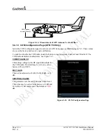
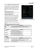
4.3.17 DME Tuning (GTN 750 only)
4.3.17.1
DME Tuning Function
The GTN 750 can channel a DME based on the tuned VLOC frequency. The GTN 750 outputs 2 of 5,
BCD, or Slip parallel DME and King Serial DME channeling format. When DME COMMON is held
low, the GTN 750 actively tunes the DME.
4.3.17.2
DME Tuning Electrical Characteristics
4.3.17.2.1 Parallel DME Tuning
Pin Name
Connector
Pin
I/O
PAR DME 100KHZ-A/NAV SERIAL DME HOLD
P1004
37
Out
PAR DME 100KHZ-B
P1004
39
Out
PAR DME 100KHZ-C
P1004
40
Out
PAR DME 100KHZ-D
P1004
42
Out
PAR DME 100KHZ-E
P1004
54
Out
PAR DME 50KHZ
P1004
43
Out
PAR DME 1MHZ-A
P1004
45
Out
PAR DME 1MHZ-B
P1004
46
Out
PAR DME 1MHZ-C
P1004
47
Out
PAR DME 1MHZ-D/NAV SERIAL DME ON
P1004
33
Out
PAR DME 1 MHZ-E
P1004
56
Out
DME COMMON
P1004
41
In
For each of the parallel DME tuning discrete outputs, the driver output voltage is not more than 1.0 V
while sinking 20 mA. The maximum off state leakage current with respect to ground is less than 10
μ
A.
DME COMMON must be pulled low to indicate to the GTN 750 that it is the device channeling the DME.
DME COMMON is considered active if either the voltage to ground is <1.9 V or the resistance to ground
is <375
Ω
. These inputs are considered inactive if the voltage to ground is 11-33 VDC.
4.3.17.2.2 King Serial DME Tuning
Pin Name
Connector
Pin
I/O
SERIAL DME – DATA
P1004
19
Out
SERIAL DME – CLOCK
P1004
18
Out
SERIAL DME- RNAV/CH REQ
P1004
20
In
SERIAL DME - RNAV MODE
P1004
21
In
DME COMMON
P1004
41
In
SERIAL DME – DME REQUEST
P1004
44
I/O
When SERIAL DME – DATA or SERIAL DME – CLOCK is asserted high and driving a 360
Ω
load, the
driver output voltage is not less than 8 V, and when asserted low is not greater than 10 mV.
SERIAL DME – RNAV/CH REQ, SER DME – RNAV MODE, and DME COMMON are considered
active if either the voltage to ground is <1.9 V or the resistance to ground is <375
Ω
. These inputs are
considered inactive if the voltage to ground is 11-33 VDC.
DME COMMON must be pulled low to indicate to the GTN 650/750 that it is the device channeling the
DME.
Summary of Contents for GTN 725
Page 1: ...190 01007 02 TBD 2010 Rev A GTN 725 750 TSO Installation Manual GTN 725 and GTN 750...
Page 2: ......
Page 177: ......
Page 178: ......