


Page 2-10
GTN 725/750 TSO Installation Manual
Rev. A
190-01007-02
2.4.3
VOR/LOC Antenna Location
The GTN VOR/LOC antenna should be well removed from all projections, engines and propellers. It
should have a clear line of sight if possible. The antenna must be mounted along the centerline of the
aircraft, minimizing the lateral offset.
2.4.4
Glideslope Antenna Location
The GTN Glideslope antenna should be well removed from all projections, engines and propellers. It
should have a clear line of sight if possible.
2.4.5 Electrical
Bonding
No special precautions need to be taken to provide a bonding path between the GPS antenna and the
aircraft structure. Follow the manufacturers’ instructions for the COM, VOR/LOC and Glideslope
antennas.
2.4.6
Interference of GPS
On some installations, VHF COM transceivers, Emergency Locator Transmitter (ELT) antennas, and
Direction Finder (DF) receiver antennas can re-radiate through the GPS antenna. The GTN COM does
not interfere with its own GPS section. However, placement of the GPS antenna relative to a COM
transceiver and COM antenna (including the GTN COM antenna), ELT antenna, and
DF receiver antenna is critical.
Use the following guidelines, in addition to others in this document, when locating the GTN and its
antennas.
•
GPS Antenna—Locate as far as possible from all COM antennas and all COM transceivers
(including the GTN COM), ELT antennas, and DF receiver antennas. The GPS antenna is less
susceptible to harmonic interference if a 1.57542 GHz notch filter is installed on the COM
transceiver antenna output.
•
Locate the GTN as far as possible from all COM antennas.
If a COM antenna is found to be the problem, a 1.57542 GHz notch filter (Garmin P/N 330-00067-00)
may be installed in the VHF COM coax, as close to the COM as possible. This filter is not required for
the GTN transmitter.
If a COM is found to be radiating, the following can be done:
1.
Replace or clean VHF COM rack connector to ensure good coax ground.
2.
Place a grounding brace between the GTN, VHF COM and ground.
3.
Shield the VHF COM wiring harness.
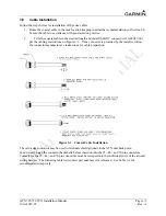
COM, VOR/LOC, and Glideslope Antenna Installation Instructions
Install the COM, VOR/LOC, and Glideslope antennas according to the manufacturer’s recommendations.
Avoid running other wires and coaxial cables near the VOR/LOC antenna cable.
Summary of Contents for GTN 725
Page 1: ...190 01007 02 TBD 2010 Rev A GTN 725 750 TSO Installation Manual GTN 725 and GTN 750...
Page 2: ......
Page 177: ......
Page 178: ......


