System Configuration/Checkout
GDL 69/69A Installation Manual
Page 4-1
190-00355-02
Revision E
4 SYSTEM
CONFIGURATION/CHECKOUT
4.1 Post-Installation
Power
Check
Move the aircraft outside and ensure that there is an unobstructed view of the Southern sky. Attach a
ground power cart to the external power connector on the aircraft and apply power.
NOTE
Use of an external power cart is optional in order to prevent the aircraft battery from
discharging to a critically low level.
Power on all systems and allow two to four minutes for initialization. Verify that the control/display unit
and the audio panel are connected, and operating properly. Ensure the circuit breaker for the GDL
69/69A is closed.
4.2 Initialization of Configuration Module
The GDL 69/69A requires aircraft installation information to be stored in the configuration module.
For MX20 and 400/500 series units the configuration module is installed in the back panel connector
backshell assembly and the only parameter stored in the configuration module is the variable attenuator
value needed to obtain the required GDL 69/69A gain/loss component.
For installations with the GDU 104x, the configuration information is stored with the G1000 avionics
system. Therefore the configuration module is not installed in the GDL 69/69A connector backshell. For
installations with the G1000 avionics system, the configuration information contains the variable
attenuator value and may contain several other parameters.
NOTE
The GDL 69/69A does not provide proper operation until the configuration initialization
procedure is completed.
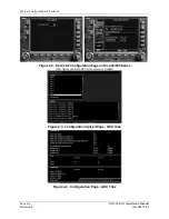
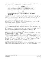
4.2.1 Configuration Module Procedure for Installation with MX20
Refer to the latest revision of the MX20 Installation Manual (Garmin AT Part Number 560-1025-( )) for
instructions.
Summary of Contents for GDL 69
Page 1: ...190 00355 02 June 2006 Revision E GDL 69 69A Installation Manual ...
Page 2: ...This Page Intentionally Left Blank ...
Page 69: ......
Page 70: ......

