Installation Procedure
Page 2-16
GDL 69/69A Installation Manual
Revision E
190-00355-02
2.6.4.2
Determining GDL 69/69A Gain/Loss Component Value
The GDL 69/69A has a zero to 10dB variable attenuator that is used to balance the gain/loss component
between its RF input and internal XM Receiver. The gain/loss components can be adjusted b6dB
and -4dB to balance the Antenna input to XM receiver 20dB gain requirement as specified for the XM
system. The Gain/Loss component is factory preset with a default value of -0.5 dB. Using the Signal
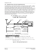
Gain Equation shown in Figure 2-9 and solving for the GDL 69/69A component the equation becomes
GLcomp in dB = XMgain – A Cable
Where:
GLcomp
– GDL 69/69A Gain/Loss Component
XMgain
– XM specified gain from antenna input to XM receiver input (20dB)
Antenna
– Antenna Gain
Cable
– Cable Loss
Example:
If the cable loss calculated in the previous example is used, the GDL 69/69A loss component is:
GLcomp
= 20dB - 25dB + 3.61dB
= -5dB + 3.61dB
= - 1.39dB
The GDL 69/69A gain/loss component will be programmed into the configuration module during post
installation checkout.
2.6.5 Coaxial
Cable
Installation
1.
Choose the correct coax: RG-400/U has good characteristics for loss, size, and flexibility.
NOTE
The cable loss of the antenna cable is critical to the performance of the GDL 69/69A
operation. To accommodate this, the GDL 69/69A has the ability to be configured for the
amount of antenna cable loss. To reduce the need to configure the GDL 69/69A for cable
loss, the GDL 69/69A is factory-preset with a cable loss of 4.5 dB, which is equivalent to
12 to 16 feet of RG-400/U with two properly terminated TNC connectors. If the cable
loss is different than the default value, the cable loss must be calculated or measured and
the loss value programmed into the GDL 69’s configuration module. Refer to Section 4.2
for additional information on determining antenna cable loss value and how to program
the configuration module.
NOTE
To avoid programming the configuration module, use a coax cable length that is within
the factory default cable loss value (refer to Section 2.6.4.1). When using the default
cable loss value, additional cable after routing through the aircraft may be coiled and
secured as needed. Do not coil the cable tighter than a one foot diameter.
2.
Trim the coaxial cable to the desired length and install TNC connectors at each end per the
cabling instructions listed in Figure 2-10. For routing convenience, one end of the coaxial run
can be terminated prior to installation.
3.
With the GDL 69/69A receiver and antenna installed, route and clamp the coaxial cable in
position. Secure cable in accordance with AC 43.13-1B, Chapter 11.
Summary of Contents for GDL 69
Page 1: ...190 00355 02 June 2006 Revision E GDL 69 69A Installation Manual ...
Page 2: ...This Page Intentionally Left Blank ...
Page 69: ......
Page 70: ......


