


190-01263-01 Rev. A
Garmin G2000 Pilot’s Guide for the Cessna T240
439
AutomAtic Flight control SyStem
Sy
Stem
o
Ver
Vie
W
Flight
in
Strument
S
ei
S
Au
D
io
P
A
nel
&
cn
S
Flight
m
A
n
Agement
hAZA
rD
AV
oi
D
A
nce
AF
cS
ADD
ition
A
l
Fe
Ature
S
APP
en
D
ice
S
in
D
eX
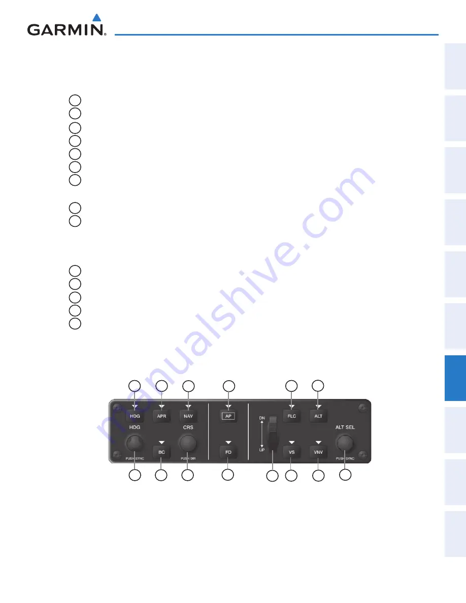
7.1 AFcS controlS
The AFCS Control Unit is positioned above the MFD, and has the following controls:
1
HDG Key
Selects/deselects Heading Select Mode
2
APR Key
Selects/deselects Approach Mode
3
NAV Key
Selects/deselects Navigation Mode
4
AP Key
Engages/disengages the autopilot
5
FLC Key
Selects/deselects Flight Level Change Mode
6
ALT Key
Selects/deselects Altitude Hold Mode
7
HDG SEL Knob
Adjusts the Selected Heading and bug in 1° increments on the HSI
Press to synchronize the Selected Heading to the current heading
8
BC Key
Selects/deselects Backcourse Mode
9
CRS Knob
Adjusts the Selected Course (while in VOR, LOC, or OBS Mode) in 1° increments
on the Horizontal Situation Indicator (HSI)
Press to re-center the Course Deviation Indicator (CDI) and return course pointer
directly TO the bearing of the active waypoint/station
10
FD Key
Activate/deactivate the flight director in default vertical and lateral modes
11
UP/DN Wheel
Adjusts the Vertical Speed Reference and bug in 100-fpm increments
12
VS Key
Selects/deselects Vertical Speed Mode
13
VNV Key
Selects/deselects Vertical Path Tracking Mode for Vertical Navigation flight control
14
ALT SEL Knob
Adjusts the Selected Altitude and bug in 100-ft increments (a finer resolution of 10
feet is available under approach conditions)
Figure 7-1 GMC 720 AFCS Control Unit
1
12
13
4
2
8
3
5
6
7
9
10
14
11
This manual downloaded from http://www.manualowl.com


