background image

Connection Diagram

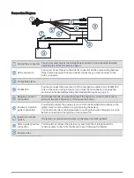
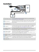
Microphone connector

You can securely mount the microphone connector in an accessible location 
(

Installing the Connector Mount, page 4

).

RCA connectors

You must connect these to the AUX IN connector on the stereo wiring harness.
If the stereo has more than one AUX IN connector, you must connect to the 
AUX1 connector.

Compatible stereo

TELEMUTE

You must connect the bare wire from the microphone cable to the TELEMUTE 
wire on the stereo wiring harness if you want the microphone to change the 
source when activated(

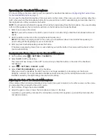
Operating the Handheld Microphone, page 7

).

Negative (-) power 
connection

For the best results, you should connect the negative (-) wire from the micro­
phone to the same negative (-) terminal as the stereo.

Positive (+) ignition 
power connection

You should connect the positive (+) wire from the handheld microphone to the 
ignition wire from the stereo to avoid draining the battery.
You must route the combined positive (+) and ignition wires through a 3 A fuse 
before connecting to the ignition or manual switch.

Ignition or manual 
switch

The ignition or manual switch turns on the stereo and microphone.

Stereo power positive 
connection

You should not connect the positive (+) wire from the microphone to the 
constant power cable from the stereo to avoid draining the battery.

Power source

6

Summary of Contents for FUSION

Page 1: ...ing to install this product CAUTION To avoid possible personal injury always wear safety goggles ear protection and a dust mask when drilling cutting or sanding NOTICE When drilling or cutting always...

Page 2: ...andheld Microphone page 7 Negative power connection For the best results you should connect the negative wire from the micro phone to the same negative terminal as the stereo Positive ignition power c...

Page 3: ...sponse From 100 Hz to 4 kHz Microphone weight 250 g 8 75 oz Output max 1 Vrms THD N Vo 1 Vrms 1 kHz Less than 0 1 Vrms Gain 18 0 5 dB Load impedance min 10k Ohm Operating voltage From 10 5 to 32 Vdc C...

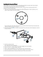
Page 4: ...th the flat surface pointing to any direction other than the left the microphone cable will not point downward when you connect it 2 Using the mounting plate as a template trace the cable hole in the...

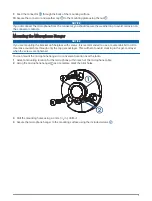
Page 5: ...rews it is recommended to use a countersink bit to drill a clearance counterbore through only the top gel coat layer This will help to avoid cracking in the gel coat layer when the screws are tightene...

Page 6: ...andheld Microphone page 7 Negative power connection For the best results you should connect the negative wire from the micro phone to the same negative terminal as the stereo Positive ignition power c...

Page 7: ...After you have finished speaking release the button If the stereo was playing music from a source before you held the button the stereo switches back to that source automatically Configuring the Fusi...

Page 8: ...hm Operating voltage From 10 5 to 32 Vdc Current at 14 4 Vdc 0 005 A Fuse not included 3 A Water rating IEC 60529 IPX7 2 2020 Garmin Ltd or its subsidiaries Garmin the Garmin logo Fusion and the Fusio...

Reviews: