


AQUAMAP™ 10x2/12x2 SERIES
7
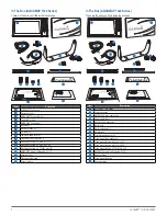
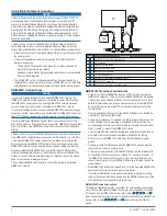
Item
Description
1
DC Power supply / battery
2
Power/NMEA 0183 cable
3
NMEA 0183 device
Item
Garmin Wire Color
Garmin Wire Function
NMEA 0183 Device
Wire Function
1
Red
Power
Power
2
Black
Power supply - / ground Power supply - / ground
3
Black
Data ground
Data ground
4
Brown
RXA (+)
TXA (+)
5
Violet
RXB (-)
TXB (-)
6
Blue
TXA (+)
RXA (+)
7
Gray
TXB (-)
RXB (-)
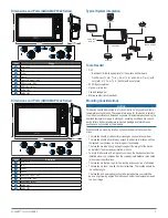
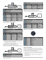
Single-Ended NMEA 0183 Device Connections
Item
Description
1
Power source
2
Power/NMEA 0183 cable
3
NMEA 0183 device
Item
Garmin Wire Color
Garmin Wire Function
NMEA 0183 Device
Wire Function
1
Red
Power
Power
2
Black
Power ground
Power ground
3
Violet
RXB
Not applicable
4
Brown
RXA
TX
5
Blue
TXA
RX
6
Gray
TXB
N/A
•
If the NMEA 0183 device has only one input (receive, RX) wire (no A, B, +,
or -), you must leave the TXB wire unconnected.
•
If the NMEA 0183 device has only one output (transmit, TX) wire (no A, B,
+, or -), you must connect the RXB wire to ground.
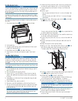
NMEA 0183 Device Connected with a Single Receive Wire
In this example, the NMEA 0183 device is receiving data from the chartplotter.
Item
Description
1
DC Power supply / battery
2
Power/NMEA 0183 cable
3
NMEA 0183 device
Item
Garmin Wire Color
Garmin Wire Function
NMEA 0183 Device
Wire Function
1
Red
Power
Power
2
Black
Power supply - / ground Power supply - / ground
3
Blue
TXA
RXA
4
Gray
TXB
Not applicable
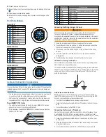
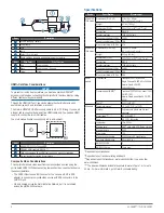
NMEA 0183 Device Connected with a Single Transmit Wire
In this example, the NMEA 0183 device is sending data to the chartplotter.
Item
Description
1
DC Power supply / battery
2
Power/NMEA 0183 cable
3
NMEA 0183 device
Item
Garmin Wire Color
Garmin Wire Function
NMEA 0183 Device
Wire Function
1
Red
Power
Power
2
Black
Power ground
Power ground
3
Violet
RXB
Not applicable
4
Brown
RXA
TXA
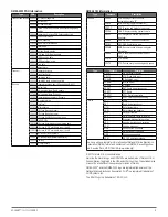
NMEA 0183 and Power Cable Pinout
Pin
Wire Color
Wire Function
1
Gray
NMEA TXB
2
Black
Ground / Power supply -
3
Blue
NMEA TXA
4
Brown
NMEA RXA
5
Yellow
Alarm
6
Red
Power
7
Violet
NMEA RXB
8
Orange
Accessory on
Lamp and Horn Connections
The device can be used with a lamp, a horn, or both, to sound or flash an
alert when the chartplotter displays a message. This is optional, and the alarm
wire is not necessary for the device to function normally. When connecting the
device to a lamp or horn, observe these considerations.
• The alarm circuit switches to a low-voltage state when the alarm sounds.
• The maximum current is 1 A, and a relay is needed to limit the current from
the chartplotter to 1 A.
• To manually toggle visual and audible alerts, you can install single-pole,
single-throw switches.
Summary of Contents for AQUAMAP 10x2 Series
Page 10: ......