background image

GPSMAP 182/182C Owner’s Manual 


39

M

AIN

 M

ENU

 > 

GPS T

AB

M

AIN

 M

ENU

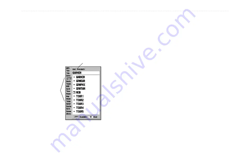
The Main Menu provides access to various waypoint, system, 

navigation, interface management, and setup menus. The 19 Menu 

tabs are divided into categories by function. The Main Menu is 

available from any page in the system, and is accessed by pressing 

MENU

 twice. See page 6 for additional instructions on changing 

settings and entering data.

Main Menu 

Tabs

Sub Tabs

Main Menu

To select a Menu tab from the Main Menu:

1.   Press up or down on the 

ROCKER

 to highlight a tab. The 

information for the highlighted tab automatically appears 

to the right. If you want to select any of the sub tab items, 

press right on the 

ROCKER

, and press up or down to select 

individual items.

2.   Either press 

MENU

 for additional submenu options, or press 

ENTER

 to make changes to the highlighted item. Press left 

on the 

ROCKER

 to get back to the Main Menu tabs list. 

3.  Press 

QUIT

 to return to the Main Menu.

Summary of Contents for 182/182C

Page 1: ...GPSMAP 182 182C chartplotting receiver owner s manual GPSMAP 182C shown...

Page 2: ...e viewed and to print one copy of this manual or of any revision hereto provided that such electronic or printed copy of this manual must contain the complete text of this copyright notice and provide...

Page 3: ...ual and learn the operating procedures for your unit in detail This manual is organized into the following sections The Introduction section contains the Table of Contents and GPSMAP 182 182C care inf...

Page 4: ...Key 12 Selecting a Go To Graphically 13 TracBack Navigation Navigating a Track 14 Routes 17 Find 19 Additional Information 21 DSC 22 Understanding Distress Calls 22 Understanding Position Reports 23...

Page 5: ...ng Sonar 89 Understanding the Sonar Display 89 Transducer Coverage 90 Whiteline 91 Thermoclines 91 Appendix 92 Speci cations 92 Installing the GPSMAP 182 182C 93 Mounting the GPSMAP 182 182C 94 Instal...

Page 6: ...a car as permanent damage can result User information such as waypoints and routes are retained in the unit s memory without the need for external power It is always a good practice to back up importa...

Page 7: ...view of the sky A full screen GPS Information Page is displayed after you press ENTER to acknowledge the Warning Page The page goes away after the unit gets a position x or you press either ENTER or...

Page 8: ...ay but rather helps to speed up the initial satellite acquisition If the unit displays Ready 2D or 3D during this process it is not necessary to initialize the unit The GPSMAP 182 182C now begins sear...

Page 9: ...OTE Do not attempt to navigate using Simulator Mode When the unit is set to Simulator Mode the GPS receiver is turned off Any satellite signal strength bars displayed are only simulations and do not r...

Page 10: ...you return to the Map Page To adjust the simulated speed and heading from the Pointer or Highway Pages 1 Press up on the ROCKER increase the speed in 10 knot kph mph increments Press down on the ROCK...

Page 11: ...ces POWER Key Press and hold to turn unit on or off Press and release to adjust backlighting IN OUT Zoom Keys From the Map Page press to zoom in or out From any other page press to scroll up or down a...

Page 12: ...that are speci c for that page To select an option requires movement of the cursor This is referred to as highlighting selecting or choosing an item 2 Use the ROCKER to move the cursor highlight up a...

Page 13: ...se the IN OUT keys to select a map scale 2 Use the ROCKER to move the pointer A data eld appears at the top of the display showing the bearing and distance from your boat to the pointer along with the...

Page 14: ...n 2D or 3D x to mark your present position This can be determined by looking at the GPS tab on the Main Menu When you move the pointer over a map item a highlighted description of that item appears Yo...

Page 15: ...m a description of the point its distance and bearing from your current location and the latitude longitude of the pointer are displayed along the top of the map To create a new waypoint graphically 1...

Page 16: ...ss the MOB key 2 Press ENTER to con rm and begin navigating to the MOB location 3 To stop navigation to the MOB location press NAV highlight Stop Navigation and press ENTER When a MOB has been activat...

Page 17: ...To access the Waypoint Edit Page 1 Use the ROCKER to highlight a waypoint on the map Or Press MENU twice highlight the Points tab and then highlight a waypoint from the User or Proximity lists 2 Pres...

Page 18: ...window You can also use the IN and OUT keys to zoom the map The map scale appears in the lower right corner 3 Use the ROCKER to point to the new location and press ENTER 4 To stop the move process pre...

Page 19: ...o Graphically A graphical Go To can be used to select one of three items from the map display an existing waypoint on screen map items such as roads rivers cities and navaids or a new map point If you...

Page 20: ...your path using the track log automatically stored in the receiver s memory This feature eliminates the need to store waypoints along the way TracBack routes are created by reducing your track log in...

Page 21: ...s ENTER 3 From the Save Back Through window highlight time date or Entire Log and press ENTER When the track has been saved the Save Track window is displayed The default name distance number of point...

Page 22: ...s closely as possible To get the most out of the TracBack feature remember the following tips Always clear the track log at the starting point The Record Mode option on the track log setup page must b...

Page 23: ...ge or highlight the rst available blank route slot and press ENTER Skip to step 4 if you use this method 3 Select the New Route option and press ENTER 4 To add an existing waypoint or map item to the...

Page 24: ...te Review Page 1 Press MENU twice to display the Main Menu 2 Use the ROCKER to highlight the Route tab and press MENU to display the route options page or highlight the rst available blank route slot...

Page 25: ...ewing to return to the Waypoint Review Page Press ENTER to add the point to the route The next eld automatically highlights 8 Repeat steps 5 7 until all the route points are entered Press QUIT to retu...

Page 26: ...n also Find from items found on the Find List The Find option also supports a nd from feature that allows you to center your search around an item you have just found For example you search for Restri...

Page 27: ...pending on the type of data loaded on the optional data card Tabs along the top of the detail window contain the information available for the item Any additional options are displayed along the botto...

Page 28: ...he caller The rescuer can then choose to navigate to the caller s location to assist or forward the call on to the Coast Guard When the Coast Guard receives the call they can immediately access the ca...

Page 29: ...ng and Distance from your current position and the coordinates of the caller To see the caller s location on a map select the Show Map button To create a waypoint at the caller s location select the C...

Page 30: ...ceived Press MENU to sort the list and delete entries DSC Directory The DSC Directory acts much like a phone book and can hold up to 50 entries Pressing MENU from this page displays options to add a N...

Page 31: ...ess ENTER Or 1 Highlight the call on the Call List or Log and press NAV 2 With Go To MMSI Name or DSC highlighted press ENTER Navigating to a DSC Call Setting up DSC The DSC Setup sub tab allows you t...

Page 32: ...press PAGE the next main page is appears Do the same with the QUIT key QUIT acts the same as PAGE except the pages are displayed in a reverse sequence Each main page has an options menu Options menus...

Page 33: ...he map scale displays at the bottom right of the page The Zoom IN and OUT keys combined with the ROCKER allow you select zoom ranges and move the pointer Two basic map operating modes Position Mode an...

Page 34: ...osition changes as your location moves The pointer can also be used to view on screen waypoint and map item properties directly from the map display Pressing ENTER while highlighting a map item brings...

Page 35: ...con rm the new waypoint using the default three digit name and symbol For more information about waypoints see page 8 Selecting Map Zoom Range The map display has 28 available zoom ranges from 20 ft t...

Page 36: ...GPSMAP 182 182C are menu driven Each main page has an options menu allowing you to customize the corresponding page to your preferences and or select special features that speci cally relate to that...

Page 37: ...ghlight Show Data and press ENTER Change Numbers speci es the type of data displayed in each data eld used on the map display To change a data eld 1 From the menu use the ROCKER to highlight the Chang...

Page 38: ...ints on the map display To measure the bearing distance between two points 1 Highlight Measure Distance and press ENTER An on screen pointer labeled ENT REF appears on the map display at your present...

Page 39: ...your destination and current direction of travel The middle of the page features a rotating compass ring that shows your course over ground track while you are moving and a bearing pointer that indica...

Page 40: ...s on changing the data elds and layout of the Pointer Page see page 31 Numbers Page The Numbers Page allows for precision navigation to 1 degree of steerage The default page displays three large numbe...

Page 41: ...raphic steering guidance to a destination waypoint placing greater emphasis on your straight line course and the distance and direction you are off course As you head toward your destination the middl...

Page 42: ...u can zoom in or out on the Highway display for a smaller or larger view Five available settings range from 1X to 16X with a default setting of 8X The current scale appears in the bottom right of the...

Page 43: ...and layout of the Highway Page see page 31 Active Route Page The Active Route Page shows each point of the active route with the point name distance and choice of Course ETA Fuel Leg Distance Leg Fue...

Page 44: ...nvert reverses the direction of the route Re evaluate recalculates and reactivates the current route Invert reverses the route To invert an active route 1 From the Active Route Page press MENU 2 Using...

Page 45: ...ging settings and entering data Main Menu Tabs Sub Tabs Main Menu To select a Menu tab from the Main Menu 1 Press up or down on the ROCKER to highlight a tab The information for the highlighted tab au...

Page 46: ...atellite s and is collecting data Dark signal strength bars the receiver has collected the necessary data and the satellite s are ready for use Sky View Signal Strength Bars Receiver Status Differenti...

Page 47: ...in developmental service WAAS satellite signal reception requires an absolute clear view of the sky and works best when there are no nearby obstructions such as buildings and mountains WAAS satellite...

Page 48: ...metry have been acquired and a 2 dimensional position x latitude and longitude is being calculated 2D Differential appears when you are receiving DGPS corrections in 2D mode and a D shows on the stren...

Page 49: ...oise Ratio indicates on a scale to 0 30db with 30db being the best the strength of the DGPS signal being received The SNR depends on the mounting of your DGPS receiver and the distance from the DGPS t...

Page 50: ...tion time STA appearing at the bottom Daytime light bar and nighttime dark bar show across the time scale with the time progressing from left to right Local time scales and sunrise sunset info may not...

Page 51: ...low above LCL and STA indicate the maximum minimum levels respectively The four data elds below the chart indicate event times and levels the tide changes starting in the upper left eld going downward...

Page 52: ...change the date for the tide chart 1 Using the ROCKER highlight the On eld and press ENTER 2 Enter the date and press ENTER To use the current date Press MENU highlight Use Today s Date and press ENT...

Page 53: ...les Celestial Tab The Celestial tab displays celestial data for sun and moon rise set moon phase and approximate sky view location of the sun and moon The moon phase displays the current visible porti...

Page 54: ...From the Find item detail page highlight OK and press ENTER The location the unit is using appears in the Date Time Position eld The time tables displayed are based on your current time zone When usin...

Page 55: ...ROCKER to highlight the Points tab A list of stored waypoints appear to the right of the Main Menu list 2 Press right one time on the ROCKER The User tab is now highlighted 3 Press down on the ROCKER...

Page 56: ...y the waypoint menu options Using the ROCKER highlight the User tab and press MENU To scroll through and review the waypoint list 1 With the ROCKER highlight the Points tab from the Main Menu and then...

Page 57: ...ER to con rm the deletion warning To delete waypoints by symbol 1 From the User sub tab highlight the waypoint to delete and press MENU Select Delete By Symbol and press ENTER 2 Use the ROCKER to high...

Page 58: ...alerted to the closest proximity waypoint To add a proximity waypoint 1 Use the ROCKER to highlight an empty space on the Proximity list and press ENTER The Find screen appears Highlight Waypoints an...

Page 59: ...All removes all waypoints from proximity list Routes Tab The Route List Page displays all the routes currently stored in memory along with a descriptive name for each route When a route has been crea...

Page 60: ...te Route and press ENTER With OK highlighted press ENTER again to con rm a deletion Copy uses the same route name with an additional number starting at 1 at the end of the route name To delete all rou...

Page 61: ...ENTER when nished When you are on the Route Review Page you can review the route points waypoints or map items one at a time from the list To review individual route points 1 Highlight a point and pre...

Page 62: ...p item To edit the route on the map From the Route Review Page press MENU highlight Edit on Map and press ENTER To edit a route point Use the ROCKER to highlight a route waypoint and press MENU To rev...

Page 63: ...g waypoint or map item ADD is displayed below the arrow and the route lines move with the arrow and press ENTER 3 If you are not inserting an existing point press ENTER to con rm the new waypoint Add...

Page 64: ...isplay trip planning information for each leg or the entire route Available information includes Course ETA Fuel to point Leg Distance Leg Fuel Leg Time Sunrise and Sunset at point location and Time T...

Page 65: ...deleted from unit memory To delete a route 1 From the Route Review Page press MENU 2 Highlight Delete Route press ENTER and press ENTER again to con rm the deletion Track Tab The Track tab allows you...

Page 66: ...Selecting the off setting prevents you from using the TracBack feature Fill a track log is recorded until the track memory is full Wrap records the track log continuously After the available memory i...

Page 67: ...log from memory Delete All deletes all saved track logs from memory You can use the Review On Map option to display a saved track on a Track Map Page To activate a TracBack from the Saved tab list 1...

Page 68: ...racks to a data card When data is saved to a data card it can be exchanged with other compatible units and Garmin s MapSource PC program To transfer data to from a data card 1 Insert the data card Fro...

Page 69: ...light Savings Time choose from Auto On or Off to adjust for daylight saving time Pages Tab The Pages tab allows you to turn on or off any of the main pages or Jump To a particular page You can also se...

Page 70: ...rst Page Option Pages Tab Map Tab The Map tab changes the display properties of the Map Page The following pages contain descriptions of the Map tab s eight sub tabs General Sub Tab Detail Most More N...

Page 71: ...s On Off turns on or off all built in BlueChart maps To display the Map Information Page 1 Highlight the Detail option box and press ENTER 2 Use the ROCKER to scroll through the list of maps 3 To sele...

Page 72: ...the maximum scale features should appear on the Map Page Some types of data only show up at speci c zoom scales Points Sub Tab The Spot Soundings Tide Stations and Services options each contain adjust...

Page 73: ...Off draws an extension from the end of the boat icon in the direction of travel Bearing Line On Off toggles the black white line that points to the current navigation point Course Line Auto Off 120 f...

Page 74: ...on page 35 Temp Temperature Tab The Temperature tab displays the water temperature log The temperature log requires input from a temperature transducer sensor The most recent temperature measured disp...

Page 75: ...software version and prepares software update cards The following settings are available Beeper Off Alarms Only Key and Alarm controls audible beeps for keys and alarms Speed Filter Off Auto On avera...

Page 76: ...nges the coordinate system You should only change the position format if you are using a map or chart that speci es a different position format or want to use a format with which you are familiar For...

Page 77: ...determined from your current location True provides headings based on a true north reference Grid provides headings based on a grid north reference and is used in conjunction with the grid position fo...

Page 78: ...as an external Sonar Module a DGPS beacon receiver a personal computer or another Garmin unit NOTE If a DGPS receiver is used WAAS capability is automatically turned to off See pages 98 and 99 for wir...

Page 79: ...t any output capabilities NMEA In NMEA Out supports the input output of standard NMEA 0183 data and sonar NMEA input support for the DPT MTW and VHW sentences You can also adjust the NMEA output RTCM...

Page 80: ...NMEA output are available if you have one of the ports set to NMEA In NMEA Advanced NMEA settings enable disable certain sentences and adjust the number of Lat Lon output precision digits Settings af...

Page 81: ...ically scan for a frequency 1 With the unit set to Garmin DGPS or RTCM In NMEA Out use the ROCKER to highlight the Beacon eld and press ENTER 2 Highlight Scan and press ENTER The numbers in the Freque...

Page 82: ...SNR range is 0dB to 30dB with 30 being the best The Distance eld is based on the signal broadcast from the DGPS site Alarm Tab The Alarm tab allows you to de ne the alarm settings The Alarm tab is di...

Page 83: ...und when you enter an area of speci ed depth that is too shallow or too deep Enter a depth in the distance elds and use the control elds to turn the alarms on and off Water Temperature sets an alarm t...

Page 84: ...82 182C the Sonar Page is added to the page sequence To view the Sonar Page press PAGE or QUIT repeatedly until it appears Sonar Page The Sonar Page is where your GPSMAP 182 182C Sounder becomes a pow...

Page 85: ...tions and their current settings appears with the selected option highlighted 2 Press up or down on the ROCKER to select the option and press ENTER to access the adjustment window 3 To exit any of the...

Page 86: ...The Zoom setting is divided into six display levels 4X Split Zoom Display Dual Frequency Mode 2X Split shows two reduced size sonar pictures at the same time The right half of the display screen shows...

Page 87: ...ange of a zoomed display If the Zoom is set to 2X split or 4X split only the zoomed portion on the left side of the screen is affected by the change If the Zoom is set to Bottom Split or Bottom Lock S...

Page 88: ...izontal depth line across the display that is used to measure the depth of underwater objects The depth of the line appears in a box on the right side of the line Press up or down on the ROCKER to con...

Page 89: ...t Menu options and their current settings see page 79 To change an Adjustment setting 1 While on the Adjustment options list use the ROCKER to highlight the option and press ENTER 2 Use the ROCKER to...

Page 90: ...ion 3 Press ENTER MARK The New Waypoint Page appears with the waypoint s coordinates default three digit name and pointer depth automatically lled in 4 To change the name symbol or depth highlight the...

Page 91: ...n to the Sonar Page or previous page Fish Symbols determines how the Sonar Page displays underwater targets and background information If you select off the unit does not show sh symbols If you select...

Page 92: ...ff to alert you that the unit is not tracking the bottom Main Menu Sonar Tab Scale controls the depth Scale displayed vertically along the right side of the graph The depth Scale can be con gured to d...

Page 93: ...p Page sonar split range scale Full Range shows the entire scale of 2X or 4X left side split of Sonar Page Maximum Detail displays what is shown on the left side of a split sonar screen Background Col...

Page 94: ...ou can also press MENU on the calibration screen and choose Use Top Ground Speed to default back to ground speed or Use No Calibration to use the speed sensor s uncalibrated speed NOTE If the boat is...

Page 95: ...s the bottom level Weaker secondary returns provide the detailed data Stronger returns display in darker colors with red being the strongest return Understanding the Sonar Display One of the rst thing...

Page 96: ...the 40 cone angle produces a coverage area of approximately a 20 foot diameter circle at a 30 foot depth The narrow cone angles 10 associated with the high frequencies 200 kHz provide better bottom r...

Page 97: ...the bottom The unit uses the whiteline function to make the bottom layer information easier to distinguish Whiteline Off Whiteline On Thick Whiteline Hard bottom Thermoclines A rough de nition of a th...

Page 98: ...lel channel WAAS capable receiver Acquisition Times Warm Approx 15 seconds Cold Approx 45 seconds AutoLocate Approx 2 minutes Update Rate 1 second continuous GPS Accuracy Position 15 meters 49 feet 95...

Page 99: ...a where it is shaded by the boat s superstructure a radome antenna or mast Sailboat users should avoid mounting the antenna high on the mast to prevent inaccurate speed readings caused by excessive he...

Page 100: ...surface or overhead mounting When choosing a location for the display unit consider the following conditions There should be at least a 3 7 cm clearance behind the case to allow connection of the ant...

Page 101: ...veling the unit 5 Screw the two mounting knobs through the bracket and into the display case 6 Connect the power data and antenna cables external antenna only to the back of the unit making sure the l...

Page 102: ...e contacts surface The GPSMAP 182 182C with external antenna can be ush mounted on a at panel using its existing mounting bracket To ush mount the GPSMAP 182 182C 1 Remove the four M5 screws from the...

Page 103: ...ble To install the ferrite bead clamp 1 Choose a location where there is no more than two inches 5 cm from the back of the GPSMAP 182 182C 2 Remove the backing from the adhesive foam strip Place the s...

Page 104: ...2 0 Amp fuse For wiring the GPSMAP 182 182C to a GSD 20 Sonar Module refer to the GSD 20 Installation Guide PIN 2 black Ground Power and Data PIN 3 blue NMEA OUT Com 1 TX PIN 4 brown NMEA IN Com 1 RX...

Page 105: ...pts NMEA input with support for the DBT DPT DSC MTW and VHW sentences The GPSMAP 182 182C also includes NMEA input with support for the WPL sentence and sonar NMEA input with support for the DPT Depth...

Page 106: ...t is on a con rmation tone sounds and a message displays on screen noting the card details when the card is properly installed and accepted 4 Close the cover If you insert a data card and get a card f...

Page 107: ...satellite location with North or your current track at the top of the display Satellite Strength Indicator Bars The Satellite Strength Indicator Bars show the strength of the signal being received an...

Page 108: ...ntal U S and portions of Alaska For more information go to http gps faa gov Programs WAAS waas htm NOTE If you are using the GPSMAP 182 182C outside of the U S A we recommend you turn off WAAS for the...

Page 109: ...ormation on how to obtain a recreational MMSI number contact http www uscg mil rescue21 links mmsi htm or http wireless fcc gov marine U S Non Federal User Commercial users or those who travel outside...

Page 110: ...me you estimate to reach your destination waypoint based on current speed and track ETA at Destination the time you estimate to reach a Go To destination or the nal waypoint in a route ETA at Next the...

Page 111: ...elative to a ground position Also referred to as ground track Trip Odometer a running tally of distance travelled since last reset See also Odometer Total Average Speed average speed of unit for both...

Page 112: ...t is unable to continue receiving satellite signals Memory Full unit memory is full no further data can be saved Near Proximity Point you are nearing a proximity waypoint No Diff GPS Location RTCM is...

Page 113: ...ff To record more track points you need to clear the track log and turn track recording on This is only displayed when the track recording setting is set to Stop When Full Track Truncated a complete u...

Page 114: ...TDs You can display your position as a TD or enter waypoints as TDs The accuracy to be expected from this conversion is approximately 30 meters When the unit is placed in the LORAN TD format mode it s...

Page 115: ...and press ENTER 6 When nished highlight Save and press ENTER Loran TD Setup Page If the active GRI Chain secondary stations or offsets were changed since the waypoint was created the waypoint now ref...

Page 116: ...that are compatible with the GPSMAP 182 182C including MetroGuide Recreational Lakes with Fishing Hot Spots and Minnesota LakeMaster ProMap Programmable Data Cards blank data cards are available in 8...

Page 117: ...e assemble reverse engineer or reduce to human readable form the Software or any part thereof or create any derivative works based on the Software You agree not to export or re export the Software to...

Page 118: ...EXCLUSIVE REMEDY FOR ANY BREACH OF WARRANTY To obtain warranty service contact your local Garmin authorized dealer or call Garmin Product Support for shipping instructions and an RMA tracking number...

Page 119: ...y cause undesired operation This equipment generates uses and can radiate radio frequency energy and may cause harmful interference to radio communications if not installed and used in accordance with...

Page 120: ...e user is responsible for their prudent use MAP DATA INFORMATION One of the goals of Garmin is to provide customers with the most complete and accurate cartography that is available to us at a reasona...

Page 121: ...rse Line 67 Course Up 64 D Data Cards 100 Data Entry 6 Data Fields Change Numbers 31 Show 31 Split Fields 35 Date Time 101 Daylight Saving Time 63 Delete DSC Directory Item 24 Depth Line 82 DGPS 102 A...

Page 122: ...m 29 P Pages Tab 63 Page Key 5 Pointer Page 33 Options 34 Points Tab 49 Position Format 70 Position Reports 23 Power Key 5 Power On Off 1 Proximity Waypoints 52 Q Quit Key 5 R Receiving a DSC Call 25...

Page 123: ...ints 84 Units Tab 70 Unit Defaults 70 W WAAS 41 102 Disable Enable 42 Waterproof iv Water Speed 87 Water Temperature Alarm 77 Waypoints Creating 8 Creating Graphically 9 Editing 11 Enter Mark 8 Move 1...

Page 124: ......

Page 125: ......

Page 126: ...armin com Copyright 2005 Garmin Ltd or its subsidiaries Garmin International Inc 1200 East 151st Street Olathe Kansas 66062 U S A Garmin Europe Ltd Unit 5 The Quadrangle Abbey Park Industrial Estate R...

Reviews: