Troubleshooting
RTCSmp
Built-In Temperature Controlled Hold-Line
Part # 4532286 Rev 3 (6/10/14)
27
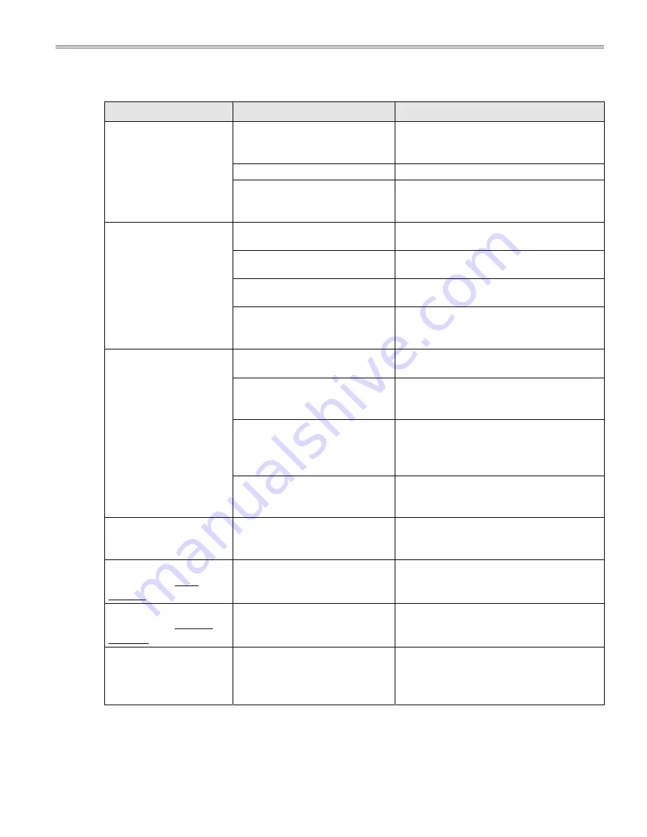
10.2
Problems and Possible Causes
Problem
Possible Causes
Action To Take By Operator
Pan does not heat, digital
display is OFF (dark)
No power supply.
Check the electrical supply, e.g. power cable
plugged into the wall socket.
Check primary fuses.
Control knob is in OFF-position.
Turn control knob to an ON-position.
Defective induction unit.
Ensure knob is in OFF-position and if possible
and safe, disconnect the unit from the power
supply. Contact your authorized service agency.
Pan does not heat.
If an error code is shown,
see next section.
Pan is too small.
Use a suitable pan with bottom diameter larger
than 5” (12cm).
Pan is not placed in the heating
zone; pan is not detected by sensor.
Place the pan in the center of the heating zone.
Unsuitable pan.
Select a pan recommended for the induction
unit.
Defective induction unit.
Ensure knob is in OFF-position and if possible
and safe, disconnect the unit from the power
supply. Contact your authorized service agency.
Poor heating, digital
display is ON (shining).
Pan is not suitable.
Select a pan recommended for the induction
unit. Then compare the results.
Air-cooling system obstructed.
Verify that air inlet and outlet are not
obstructed. Ensure the Intake Air Filter is clean.
Ambient temperature is too high;
the cooling system is not able to
keep the induction unit in normal
operating conditions.
Verify that no hot air is sucked in by the fan.
Reduce the ambient temperature. The intake air
temperature must be lower than 104°F (40°C).
Defective induction unit.
Ensure knob is in OFF-position and if possible
and safe, disconnect the unit from the power
supply. Contact your authorized service agency.
Unit does not react to
control knob positions
Defective control switch.
Ensure knob is in OFF-position and if possible
and safe, disconnect the unit from the power
supply. Contact your authorized service agency.
Power/heating level seems
to be reduced, fan is
working
Air-cooling system is blocked.
Internal fan is dirty.
Verify that air inlet and outlet are not
obstructed. Ensure the Intake Air Filter is clean.
Contact your authorized service agency.
Power/heating level seems
to be reduced, fan does
not work
Defective fan or fan control.
Ensure knob is in OFF-position and if possible
and safe, disconnect the unit from the power
supply. Contact your authorized service agency.
After a longer permanent
operating time,
Power/heating level seems
to be reduced
Overheated induction coil; cooking
area is too hot.
Overheated oil in pan.
Pan is empty.
Switch the unit off. Safely remove pan. Wait
until the heating zone has cooled down before
turning the unit ON again.
NOTE:
The fan starts when the ambient temperature in the control area exceeds 140ºF/60ºC. At heat
temperatures higher than 167ºF/75ºC, the controller automatically reduces the power to keep the unit in normal
operating conditions. The full power of the device is at heat sink temperature of 158
o
F/70
o
C, running freely again.