Part # GCTRM Rev 3 (12/10/09)
Page 33
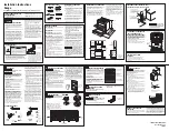
Oven Pilot
Oven pilots should reach and engulf the tip of the
thermocouple as illustrated below. If the pilot flame fully
engulfs the thermocouple premature failure will occur.
Oven Pilot
3/8" TO 1/2"
Pilot
Thermocouple
Gas Burner Control Valves
Non-adjustable Valve
Adjustable Valve
Full Range Non-adjustable Top Burner Valve
• Used for open top burners.
• Regulates the flow of gas to the burner.
• Solid “D” stem, no adjustment screw down the shaft.
• It is a fixed non-adjustable control
Adjustable Hi/Low Top Valve
• Regulates the flow of gas to manual control griddles.
• “D” stem is split containing an adjustable screw for low
position.
• Use a straight blade pocket screwdriver to adjust low
setting higher or lower.
Reminder! Adjustments on valves are for the low
flames setting only .
Full Range Non-Adjustable Control
• Used to control the flow of gas for the oven,
• Used together with the oven thermostat.
• Used fully open or fully closed (no medium setting).
• No adjustments or calibrations.
Combination Valve
• Pilot safety and gas control in one.
• Also known as “fame failure device”.
• Used together with oven thermostat on the Master Series
and ST280 Series.
• Also available on some Garland counter top models.
• Uses a magnetic coil energized by a thermocouple to
hold gas valve open.
• Cuts off gas supply when not sensing a pilot flame.
Flame Failure Devices And How They Work
There are three principles at work in a flame failure valve.
One is the thermocouple, which generates in millivoltage,
the other is the electric magnetic coil within the valve,
which holds the valve open or allows it to shut if there is no
millivoltage and the third is the valve itself.
The thermocouple is two dissimilar metals, which form
a junction, and when they are heated, they create a
millivoltage. This millivoltage, is used to power the magnetic
coil.
The thermocouple is connected to a coil, which is at most
times at the back of the valve. The coil operates on very low
millivoltage to create a magnetic field that holds a plunger
open inside the valve. If there is no millivoltage, the plunger
is released and shuts down the valve shutting off gas flow to
the pilot and burner.
Summary of Contents for G Series
Page 2: ...Part GCTRM Rev 3 12 10 09 Page 2...
Page 4: ...Part GCTRM Rev 3 12 10 09 Page 4...
Page 5: ...Part GCTRM Rev 3 12 10 09 Page 5 Section 1 Model Number Identification...
Page 17: ...Part GCTRM Rev 3 12 10 09 Page 17 Section 2 Serial Number Identification...
Page 20: ...Part GCTRM Rev 3 12 10 09 Page 20...
Page 21: ...Part GCTRM Rev 3 12 10 09 Page 21 Section 3 Certification Markings...
Page 24: ...Part GCTRM Rev 3 12 10 09 Page 24...
Page 25: ...Part GCTRM Rev 3 12 10 09 Page 25 Section 4 Properties And Characteristics of Fuel Gases...
Page 27: ...Part GCTRM Rev 3 12 10 09 Page 27 Section 5 Operation Of Controls...
Page 31: ...Part GCTRM Rev 3 12 10 09 Page 31 Section 6 Gas Valves And Adjustments...
Page 36: ...Part GCTRM Rev 3 12 10 09 Page 36...
Page 48: ...Part GCTRM Rev 3 12 10 09 Page 48...
Page 49: ...Part GCTRM Rev 3 12 10 09 Page 49 Section 8 Gas Pressure Regulators...
Page 52: ...Part GCTRM Rev 3 12 10 09 Page 52...
Page 53: ...Part GCTRM Rev 3 12 10 09 Page 53 Section 9 Thermocouples And How They Work...
Page 55: ...Part GCTRM Rev 3 12 10 09 Page 55 Section 10 Trouble Shooting The Oven Pilot Safety System...
Page 65: ...Part GCTRM Rev 3 12 10 09 Page 65 Section 13 Gas Technician s Glossary...
Page 70: ...Part GCTRM Rev 3 12 10 09 Page 70...
Page 71: ...Part GCTRM Rev 3 12 10 09 Page 71 Section 14 Range Wiring Diagrams...
Page 75: ...Part GCTRM Rev 3 12 10 09 Page 75 3056100 US Range C836C Cuisine Series...
Page 76: ...Part GCTRM Rev 3 12 10 09 Page 76 229064 US Range 836C Cuisine Series...
Page 77: ...Part GCTRM Rev 3 12 10 09 Page 77 2706601 US Range Px S Series Left Single RC Oven...
Page 78: ...Part GCTRM Rev 3 12 10 09 Page 78 2706602 US Range Px S Series Right Single RC Oven...
Page 79: ...Part GCTRM Rev 3 12 10 09 Page 79 2706603 US Range Px S Series 2 RC Ovens...
Page 80: ...Part GCTRM Rev 3 12 10 09 Page 80 4514771 US Range Px SX Series Left Single RC Oven...
Page 81: ...Part GCTRM Rev 3 12 10 09 Page 81 4514772 US Range Px SX Series Right Single RC Oven...
Page 82: ...Part GCTRM Rev 3 12 10 09 Page 82 4514774 US Range Px SX SeriesTwo RC Ovens...
Page 83: ...Part GCTRM Rev 3 12 10 09 Page 83 2529700 ME MSTE 40RC Electric Spark...
Page 84: ...Part GCTRM Rev 3 12 10 09 Page 84 2529701 M MS 40RC...
Page 85: ...Part GCTRM Rev 3 12 10 09 Page 85 2529600 M MS 40 Electric Spark...
Page 86: ...Part GCTRM Rev 3 12 10 09 Page 86 2444200 Sentry Electric Spark...
Page 87: ...Part GCTRM Rev 3 12 10 09 Page 87 2444300 STE286RC STE284RC Left ST283RCE...
Page 97: ...Part GCTRM Rev 3 12 10 09 Page 97 Section 15 Service Bulletins...
Page 108: ......