Part # GCTRM Rev 3 (12/10/09)
Page 30
5. To shut the pilot completely off, extinguish the pilot
flame. The internal pilot valve will automatically close
within 60 seconds. Each time this is done, the pilot will
have to be re-lit.
NOTE: This procedure is the same for the convection models
with SIT controls.
Range Base Convection Ovens “RC”
This section pertains to the forced air unit .
For 115 V usage, a cord and plug are provided but
connection to the electrical service must comply with local
codes; or in the absence of local codes, with the National
Electrical Code, ANS/NFPA No. 70-(current edition).
A wiring diagram is attached to the rear of this unit for your
use.
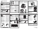
Lighting Instructions
1. Use the access though the louver panel, hold the reset
button (RED) located on the oven safety valve.
2. Using the access hole located below the louver in the
panel, push the RED IGNITOR BUTTON continuously
until the oven pilot ignites.
3. If the pilot does not stay lit after you release the reset
button, wait 5 minutes and repeat Step 2 and hold the
reset button approximately 60 seconds.
PILOT
IGNITOR
BUTTON
REST
BUTTON
ON SAFETY
Lighting Instructions
1. Use the access though the louver panel, hold the reset
button (RED) location on the oven safety valve. (See prior).
2. Using the access hole located below the louver in the
panel, push the RED IGNITOR BUTTON continuously
until the oven pilot ignites. (See Prior)
3 If the pilot does not stay lit after you release the reset
button, wait 5 minutes and repeat Step 2 and hold the
reset button approximately 60 seconds.
Start Up .
1 Activate the power switch to the cook position.
2. Turn the oven valve on. Turn the thermostat to the
desired setting.
Cool Down
1. Turn the thermostat and oven valve off.
2. Open the door.
3. Activate the power to the cool down position.
Shut down
1 Turn the thermostat off.
2. Return the power switch to the “OFF” position.
3. Turn the oven valve off
The motor on the range convection oven is maintenance free
since it is constructed with sealed ball bearings. It is designed
to provide durable service when treated with ordinary care.
We have a few suggestions to follow on the care of your
motor.
A.
Never
operate the oven without convection oven fan.
Use of this oven without the convection fan will cause
premature motor failure!
B. When the motor is operating, it cools itself internally by
air entering the rear of the motor case, provided proper
clearance has been allowed.
C. Since the blower wheel is in the oven cavity, it is at the
same temperature as the oven. If the motor is stopped
while the oven is hot, the heat from the blower wheel is
conducted down the shaft and into the armature of the
motor. This action could shorten motor life.
D. We recommend that at the end of the bake or roasting
period, when the oven will be idle for any period of time,
or before shutting down completely, that the doors
be left open, and by use of the cool-down position on
the fan switch, the fan continues to run for at least 20
minutes. The “FAN” should never be turned “OFF” when
the oven is “HOT”.
Summary of Contents for G Series
Page 2: ...Part GCTRM Rev 3 12 10 09 Page 2...
Page 4: ...Part GCTRM Rev 3 12 10 09 Page 4...
Page 5: ...Part GCTRM Rev 3 12 10 09 Page 5 Section 1 Model Number Identification...
Page 17: ...Part GCTRM Rev 3 12 10 09 Page 17 Section 2 Serial Number Identification...
Page 20: ...Part GCTRM Rev 3 12 10 09 Page 20...
Page 21: ...Part GCTRM Rev 3 12 10 09 Page 21 Section 3 Certification Markings...
Page 24: ...Part GCTRM Rev 3 12 10 09 Page 24...
Page 25: ...Part GCTRM Rev 3 12 10 09 Page 25 Section 4 Properties And Characteristics of Fuel Gases...
Page 27: ...Part GCTRM Rev 3 12 10 09 Page 27 Section 5 Operation Of Controls...
Page 31: ...Part GCTRM Rev 3 12 10 09 Page 31 Section 6 Gas Valves And Adjustments...
Page 36: ...Part GCTRM Rev 3 12 10 09 Page 36...
Page 48: ...Part GCTRM Rev 3 12 10 09 Page 48...
Page 49: ...Part GCTRM Rev 3 12 10 09 Page 49 Section 8 Gas Pressure Regulators...
Page 52: ...Part GCTRM Rev 3 12 10 09 Page 52...
Page 53: ...Part GCTRM Rev 3 12 10 09 Page 53 Section 9 Thermocouples And How They Work...
Page 55: ...Part GCTRM Rev 3 12 10 09 Page 55 Section 10 Trouble Shooting The Oven Pilot Safety System...
Page 65: ...Part GCTRM Rev 3 12 10 09 Page 65 Section 13 Gas Technician s Glossary...
Page 70: ...Part GCTRM Rev 3 12 10 09 Page 70...
Page 71: ...Part GCTRM Rev 3 12 10 09 Page 71 Section 14 Range Wiring Diagrams...
Page 75: ...Part GCTRM Rev 3 12 10 09 Page 75 3056100 US Range C836C Cuisine Series...
Page 76: ...Part GCTRM Rev 3 12 10 09 Page 76 229064 US Range 836C Cuisine Series...
Page 77: ...Part GCTRM Rev 3 12 10 09 Page 77 2706601 US Range Px S Series Left Single RC Oven...
Page 78: ...Part GCTRM Rev 3 12 10 09 Page 78 2706602 US Range Px S Series Right Single RC Oven...
Page 79: ...Part GCTRM Rev 3 12 10 09 Page 79 2706603 US Range Px S Series 2 RC Ovens...
Page 80: ...Part GCTRM Rev 3 12 10 09 Page 80 4514771 US Range Px SX Series Left Single RC Oven...
Page 81: ...Part GCTRM Rev 3 12 10 09 Page 81 4514772 US Range Px SX Series Right Single RC Oven...
Page 82: ...Part GCTRM Rev 3 12 10 09 Page 82 4514774 US Range Px SX SeriesTwo RC Ovens...
Page 83: ...Part GCTRM Rev 3 12 10 09 Page 83 2529700 ME MSTE 40RC Electric Spark...
Page 84: ...Part GCTRM Rev 3 12 10 09 Page 84 2529701 M MS 40RC...
Page 85: ...Part GCTRM Rev 3 12 10 09 Page 85 2529600 M MS 40 Electric Spark...
Page 86: ...Part GCTRM Rev 3 12 10 09 Page 86 2444200 Sentry Electric Spark...
Page 87: ...Part GCTRM Rev 3 12 10 09 Page 87 2444300 STE286RC STE284RC Left ST283RCE...
Page 97: ...Part GCTRM Rev 3 12 10 09 Page 97 Section 15 Service Bulletins...
Page 108: ......