background image


31

V. Troubleshooting the Fixture 

In the event that you should have trouble during set up or after the system has 
been in operation, there are a number of ways to isolate the problem and remedy 
the situation. 
 

A. Power Check 

Whether a single fixture goes down or the entire system fails to respond, the first 
thing to do is to check the power. When the power is connected and the on/off 
switch is in the on position, the red power switch is illuminated. If the power 
switch is not illuminated, check the breaker panel to make sure the circuit is on 
and the breaker has not tripped. If it has tripped, turn it back on and see if it 
holds. If it does not hold, unplug the fixture and try it again. If it holds without the 
fixture plugged in but not when the fixture is plugged in, then the power supply in 
the fixture should be serviced. 
 
If the circuit breaker has not tripped but the fixture is not powered, check the 
main fuse in the base of the fixture using a continuity checker. 
 

Note: A visual inspection of the fuse does not always 
determine if it is good. The only positive way to check a 
fuse is with an ohm meter or a continuity checker. 


Replace the fuse only with a 15-amp, 250V ¼” x 1-1/4” ceramic fast blow fuse 
such as a Buss ABC-15. 
 

B. Data Check 

The second thing you should always check after checking power in a non-
responsive fixture is the data connection. If the fixture is receiving data, then the 
menu display will be lit solidly. If there is no data, e.g. if the controller is turned off 
or if the data cable is unplugged or broken, then the menu display will blink 
slowly. If the menu display is blinking, then try unplugging the data cable from a 
nearby fixture and plugging it into the non-responsive unit. If that solves the 
problem, then chances are you have a bad data cable. 
 

C. Fixture Check 

If the power and data are confirmed good yet the fixture is still unresponsive, 
then you can test the fixture by resetting it from the controller or using the demo 
mode in the menuing system. (See 

demo 

in 

Setting the Fixture Personality 

above) 

!

Summary of Contents for GKH 575

Page 1: ...www maxx tech com Garkinhall Systems Inc 2006 All Rights Reserved The specifications and information supplied in this document are subject to change without notice Garkinhall Systems Inc assumes no r...

Page 2: ...size and voltage rating only Eye Protection Required Caution Risk of ultraviolet UV exposure Looking directly at light source without protection may cause retina damage Do not attempt to open fixture...

Page 3: ...nality Settings 11 J Setting the DMX512 Address 23 II Rigging the Fixture 25 III Cabling the Fixture 26 A Data Termination 26 IV Operating the Fixture 28 A DMX512 Protocol 28 V Troubleshooting the Fix...

Page 4: ...he built in diagnostic features speed troubleshooting and minimize down time The GKH 575 Color Wash is ideally suited for a variety of applications where soft edge dichroic color mixing is needed incl...

Page 5: ...Omega rigging brackets with quarter turn fasteners 4 safety cable 5 User manual C Before Applying Power Once you have made a visual inspection of the packaging and the fixture you should set it up an...

Page 6: ...the lamp with your bare hands wear gloves or use a protective sleeve to hold the lamp hold the ceramic base of the lamp and insert it into the lamp socket until it is seated completely d Replace the...

Page 7: ...splay on the base will display the default DMX512 address 001 F Aligning the Lamp Before operating the fixture for the first time and each time after the lamp is changed it is critical that the lamp i...

Page 8: ...OWN button several times until the display says dinr dimmer f Press the ENTER button g Press and hold the UP button until the display reaches the number 255 If you pass it press the DOWN button until...

Page 9: ...g the Fixture Personality below H Setting the Fixture Personality The GKH 575 Wash fixture has several customizable attributes that allow you to configure the personality of the fixture to meet the re...

Page 10: ...yEL 5 CSPd CSP 1 CSP 5 MACr OFF MA 1 MA 30 EFEC HOLE SHA 1 SHA 2 SHA 3 FroS Z oom Z oo 0 Z oo 4 Stro OPEn Str 1 Str 9 increasing strobe speed dimr dim 0 dim 5 LA Au Po0n EnSN dM In Pan 0 255 t t 0 25...

Page 11: ...t any time during the processes listed below pressing the MODE button will cancel the pending setting and exit to the next highest menu level A001 DMX512 Address The current DMX512 address setting Thi...

Page 12: ...etting allows you to choose between 16 bit resolution and 8 bit resolution 16 bit resolution requires two channels for pan course and fine adjust and two channels for tilt course and fine adjust but i...

Page 13: ...xture It is non resettable To display the number of hours of operation 1 Press the UP or DOWN button until the display reads POti 2 Press the ENTER button The display will show four digits indicating...

Page 14: ...tilt position of the head 11 Press the UP or DOWN button until the fixture is tilted to the desired position 12 Press the ENTER button 13 Press the UP or DOWN button until the display reads Z oom 14 P...

Page 15: ...tions for each function are listed below MAnu Manual operation This setting allows you to manually recall factory presets for every function of the luminaire including pan tilt speed of movement color...

Page 16: ...color settings listed below by using the UP and DOWN buttons until the display reads MAGE and then pressing the ENTER button Use the UP and DOWN buttons to select the desired magenta setting MAG 0 MA...

Page 17: ...TER The display will then go back to the next highest menu level Stro strobe Choose one of nine strobe settings plus no strobe listed below by using the UP and DOWN buttons until the display reads Str...

Page 18: ...turned Off then the heat error message will only appear if the lamp has been turned off from the controller or the menu display and turned back on within five minutes It will not automatically detect...

Page 19: ...s mode DiSP Display functions This function allows you to set up the LED menu display according to your needs There are three attributes of the display that may be adjusted the orientation of the disp...

Page 20: ...set the intensity of the display in five increments of 20 To change the intensity setting of the display 1 Select the d Int option from the SPEC function of the display see SPEC above 2 Press the ENTE...

Page 21: ...ENTER button The display will indicate the current temperature in degrees Celsius 3 Press the MODE button twice to back out of the special functions mode Fan S Fans settings This setting allows you t...

Page 22: ...the fan is automatically adjusted to its highest speed setting 4 Press the ENTER button 5 Press the MODE button twice to back out of the special functions mode dF SE Default settings This setting ret...

Page 23: ...d dimr dimmer 4 Press the ENTER button The display will show the current value in the range of 0 255 5 Press the UP or DOWN button to adjust the setting to the desired value 6 Press the ENTER button 7...

Page 24: ...ss begin with the first address and add 16 channels for each fixture Each address should be unique and the 16 channel blocks should not overlap It is often easier to set the DMX512 starting address on...

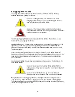
Page 25: ...he Omega bracket and into the clamp Tighten securely Fasten the two Omega brackets with clamps under the base of the fixture by inserting both quarter turn fasteners into the mounting holes on the bot...

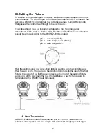
Page 26: ...s should be wired according to the DMX512 1998 standard pin 1 common shield pin 2 data complement data 1 pin 3 data true data 1 Run the control signal in a daisy chain fashion starting from the contro...

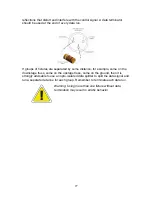
Page 27: ...y some distance for example some on the downstage truss some on the upstage truss some on the ground then it is strongly advisable to use an opto isolated data splitter to split the data signal and ru...

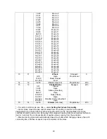
Page 28: ...28 3 2 0 255 Tilt Proportional 128 4 0 255 Tilt fine Proportional 128 5 3 0 1 249 250 255 Speed pan tilt Max speed tracking mode Vector mode2 max min Blackout during movement3 tracking mode Proportion...

Page 29: ...5 15 13 0 31 32 63 64 95 96 127 128 159 160 191 192 223 224 255 Shutter Strobe Closed Open Strobe slow fast Open Pulse effects Open Random strobe slow fast Open Stepped 255 16 14 0 255 Dimmer min max...

Page 30: ...the lamps are on Select all fixtures and using the control channel channel 6 in 16 bit mode channel 4 in 8 bit mode set the value between 128 139 You should see each fixture reset itself and in a cou...

Page 31: ...in the base of the fixture using a continuity checker Note A visual inspection of the fuse does not always determine if it is good The only positive way to check a fuse is with an ohm meter or a conti...

Page 32: ...ensor will automatically turn off the lamp and the fixture overheating error will be displayed When the temperature drops to a suitable level then the display will change to a heat error indicating th...

Page 33: ...Er Motherboard error The main PC board is not communicating correctly with the communications board Check the main PC board and or the comm board PAEr Pan error The panning mechanism has an optical en...

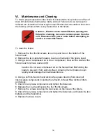
Page 34: ...lamshell housing covers on the back of the fixture head 3 Using a can of compressed air or an air compressor blow out the inside of the fixture head to remove dust and dirt Caution Do not use compress...

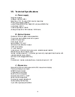
Page 35: ...nti reflection coated CMY color mixing 31 color macros Color wheel 7 dichroic colors plus open variable speed rotation Effects wheel beam shaper frost Strobe variable speed 1 10 flashes per second pre...

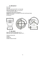
Page 36: ...ment resolution Automatic pan tilt position correction Rigging floor mount or structural mount with two Omega clamps Weight 84 pounds Dimensions 18 21 75 280 265 14 25 17 75 E Operation Maximum ambien...

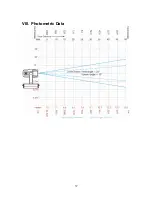
Page 37: ...37 VIII Photometric Data...

Page 38: ...38...

Reviews: