


9
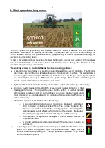
5.
Getting to work in the field
The most important procedure to ensure good guidance is to match the template, as illustrated by
the green lines, to crop rows as they appear in the live video image. The following steps outline
how to get the best match and hence achieve good guidance.
Tip
For the first few hundred meters of running after commissioning Robocrop learns a term known as
camera skew (see section 7.3) Camera skew compensates for minor errors in camera orientation
in the horizontal plane. Wherever possible we recommend that set up runs (step 4) are conducted
in crop showing the clearest rows available so that camera skew is learned as quickly and
accurately as possible. High visibility rows also help manual alignment checks (step 3). We also
recommend that side slopes and intense partial shadows are avoided during initial running. Once
set up is complete more challenging situations can be tackled. It is also possible to view the
current value of camera skew and reset it manually (see section 7.3).
Step 1
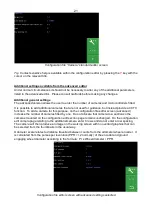
– Selecting configuration file and crop size
From the working screen press button labelled with a spanner symbol to reach the setup screen.
The top line of this screen indicates crop size (height) settings under categories of small (<5cm)
medium (5-15cm) and large (>15cm). The second line lists the available configuration files. Use
the buttons labelled with arrows to ensure that the highlighted options correspond to the crop and
crop size being used for setup and initial running.
Check details at the bottom of the screen to ensure selected configuration file settings match crop
and camera geometry.
If either crop geometry or configuration settings are not correct refer to section 7 for instructions on
making the necessary changes.
To return to the working screen by pressing the button
labelled “OK”.
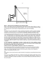
Step 2
– Checking camera height and inclination angle in the field
Draw into the crop and set the cultivator down onto a typical section of crop row. The cultivator
should be level and set onto the rows as accurately, and as straight as possible with the camera at
its normal operating height
(displayed in the “set up” screen).
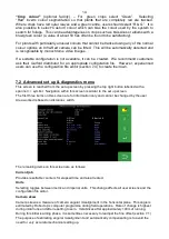
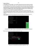
Press button labelled
“Manual”, The overlaid green lines representing the template should lock in
the centre of the screen.
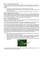
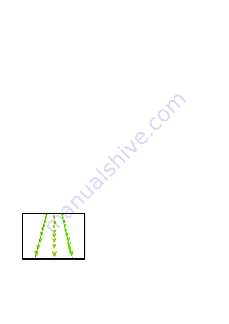
Green lines superimposed over the live image should align with crop rows as illustrated below.
Tip
If crop rows are difficult to see in the live video image you can enhance them by placing high
visibility objects such as a strip of wood exactly over the row centre line.
Caution
If the overlaid green lines are not symmetrical on the screen (by more than 4 degrees) the camera
skew value may need resetting. Refer to the advanced set up & diagnostics menu in section 7.3.
✓


