Garford Robocrop Manual Download Page 26


26 


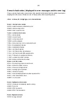
Console fault codes (displayed in error messages and the error log) 

These numeric fault codes can provide more specific information that the written description 
displayed on the screen.  Make a note of these codes when reporting errors. 


cttnn  c=class, tt= 2 digit type, nn= channel/index 


0xxxx   internal error codes  

00100   state/covariance dimension error   

00200   variance sign error  

00300   other numeric error  

1xxxx   camera error codes  

101xx   excess skew  

10300   no port found  

10400   no devices at all  

10500   just the adaptor  

106xx   some devices, but no cameras found  

107xx   Unsupported camera  

108xx   Initialisation failure  

109xx   can't start capture  

110xx   can't start video transmission  

111xx   can't work out GUID assignments  

112xx   Timeout on a particular camera  

11300   no data from ANY camera  

11400  camera connection too slow 

2xxxx  uc error codes  

201xx   the device you want is not found  

202xx   timeout on data  receive  

203xx   timeout on diag receive  

204xx   missing sync in packet  

205xx   checksum wrong  

206xx   received data packet not what we asked for  

207xx   other data format error  

20800   no uCs at all  


4xxxx  hardware error codes  

40100   odometer consistently seems wrong  

40200   Pot error  

40300   CPU fan alarm 

40400   CPU Thermal alarm 


5xxxx  Operator errors  

50100   Going too fast! 

Summary of Contents for Robocrop

Page 1: ...possible that under some adverse circumstances the guidance system will be unable to operate reliably It is the operator s responsibility at all times to ensure that the machine is operating in a sat...

Page 2: ...ep 3 Initial running and adjusting camera lateral position 11 6 Notes on operation with a correctly set up machine 12 7 Information screens and menus 13 Setup menu 14 Advanced set up diagnostics menu...

Page 3: ...ult your Garford dealer for systems to work in red crops Robocrop locates crop rows within a scene by matching a template corresponding to the known planting pattern with crop rows as they appear in t...

Page 4: ...camera field of view 2 Never conduct maintenance work on the side shift mechanism while it is supporting the implement 3 The side shift and steered disc mechanisms forms pinch trap and shear points Be...

Page 5: ...ment of the lower link arms Caution For side shifting front mounted systems it is particularly important that there is no lateral movement in the linkage Step 4 Levelling the implement With the cultiv...

Page 6: ...teered discs should centralise If the side shift or discs were already central and you wish to test them press the second touch screen button from the bottom on the right labelled manual The hydraulic...

Page 7: ...atch Systems with multiple cameras display live thumbnail videos along the top of the display An image quality gauge to the left of the screen giving relative indication of likely tracking performance...

Page 8: ...buttons For disk steered machines this is achieved by automatically steering the discs to maintain the desired slide position To prevent mechanical damage these functions only operate when lifted or...

Page 9: ...5cm and large 15cm The second line lists the available configuration files Use the buttons labelled with arrows to ensure that the highlighted options correspond to the crop and crop size being used f...

Page 10: ...up screen and make a note of a distance called look ahead Return to the working screen and press Sk5 labelled manual Purple cross hairs will appear in the image Now mark a point on the ground directly...

Page 11: ...de shift in steps of 1cm 3 8 Continue down the field stopping occasionally to check lateral position If the required fine offset exceeds the available number of steps the camera should be physically m...

Page 12: ...ave been made to camera position Operating on side slopes will result in some lateral error due to the tractor crabbing across the slope Normally this is not significant but in extreme cases it may be...

Page 13: ...opriate setting it can be selected by pressing the button labelled OK Crop size increases template size to compensate for the crop canopy getting closer to the camera as it grows This avoids the need...

Page 14: ...te their own 7 2 Advanced set up diagnostics menu This screen is reached from the set up screen by pressing the top right button labelled with a spanner symbol Navigation within this screen is similar...

Page 15: ...te mechanical setting up Camera skew relates to camera offset so that resetting skew resets both figures for all cameras fitted However resetting offset does not automatically reset skew Custom colour...

Page 16: ...ected Yes the side shift or steering discs will centralise whenever manual is selected If No is selected the side shift or discs will stay in their current position until a manual steering input is ma...

Page 17: ...le pre entered configuration files in blue text Touching on a file name selects that file highlights it in white and prefixes it with a character Buttons on the right hand side of the screen perform a...

Page 18: ...ed will change the language used The bottom button labelled with a loop back arrow returns to the start menu Note When you next run the system you need to select the appropriate configuration file as...

Page 19: ...central position distance between the steering disc pivot axis and disc ground contact point and calibration of the rotary potentiometer that measures steer angle Configuration file Section standard...

Page 20: ...symmetrical about the centre line and starts with the central row spacing working out to the edge Figures are comma delimited In the case of an even number of rows the first figure is always the whol...

Page 21: ...function To add a camera for this purpose on the configuration file editor screen advanced increase the number of cameras fitted by one Do not allocate that camera to a section so the cameras mounted...

Page 22: ...section should take its lift status and odometric speed If no microcontroller number is given for the odometer odometric speed will be calculated from the flow of features through successive images Fi...

Page 23: ...further optional graphical tool can be enabled allowing that custom hue to be varied from the advanced settings screen There are two options relate to customising fine offset which can be useful if e...

Page 24: ...to select a service option by touching the tools button which offers the following service tools View archived logs This displays a list of error messages that have been cleared from the log file Back...

Page 25: ...that it is waiting for CAN devices to register It will then normally go into a period of slow blinks 1 6 s on 1 6 s off on a continuous cycle indicating that the system is ready but idle with no dema...

Page 26: ...evices but no cameras found 107xx Unsupported camera 108xx Initialisation failure 109xx can t start capture 110xx can t start video transmission 111xx can t work out GUID assignments 112xx Timeout on...

Page 27: ...ont panel button down for about 3 secs until a black text screen appears When shut down check camera connections and restart If problem persists consult your dealer For additional problems consult the...

Page 28: ...a similar value to the tractors and does the stopped brake icon disappear when moving Check the odometer wheel is touching the ground and rotating Ensure it is not damaged and correctly connected If...

Page 29: ...ulic flow rate may be set too high low run hydraulic test from the advanced diagnostics menu Ensure that steering or stabilizer discs engage soil adequately and that check chains are tight If problems...

Page 30: ...30 Garford Farm Machinery Frognall Deeping St James Peterborough PE6 8RR England Tel 01778 342642 Fax 01778 348949 Email info garford com...

Reviews: