3
1.2 Mounting
Mount the dryer on a level solid surface. Holes are provided in the
dryer base to permanently mount the dryer to the floor.
1.3 Piping Connections
A. Air Inlet - Connect compressed air line from air source to air
inlet.
Refer to Serial Number Tag for maximum working
pressure. Do not exceed dryer’s Maximum Working Pressure.
NOTE: Install dryer in air system at highest pressure possible
(e.g. before pressure reducing valves).
NOTE: Install dryer at coolest compressed air temperature
possible. Maximum inlet compressed air temperature: 120°F
(49°C). If inlet air exceeds this temperature, precool the air with
an aftercooler.
B. Air Outlet - Connect air outlet to downstream air lines.
C. Bypass piping - If servicing the dryer without interrupting the
air supply is desired, piping should include inlet and outlet
valves and an air bypass valve.
D. Water-cooled models - cooling water inlet and outlet
1. Connect cooling water supply to cooling water inlet.
2. Connect cooling water return line to cooling water outlet
connection.
NOTE: Strainer and water regulating valve are supplied on water-
cooled models. Also, it is recommended to add water inlet/outlet
temperature and pressure gauges to the water piping.
1.4 Electrical Connections
IMPORTANT: Use copper supply wires only.
A.
Dryer is designed to operate on the volt-
age, phase, and frequency listed on the
serial number tag.
B. Electrical entry is through a hole in the
top of the cabinet. Route wires through
the bottom of the electrical enclosure.
Connect power source to the terminal strip in the electrical
enclosure as shown on the electrical schematic included with
the dryer.
NOTE: Refrigeration condensing unit is designed to run
continuously and should NOT be wired to cycle on/off with the
air compressor.
1.5 Electronic Demand Drain
A. An automatic electric demand drain (EDD)
discharges condensate removed by the
separator.
B. All dryer models are supplied with one
EDD. Models with the additional (optional)
oil removal filter are supplied with a second
EDD.
C. The drains are piped to fittings in the leg of the unit. Con
-
densate should be piped from this fitting to an open vented
floor drain or sump.
NOTE: Discharge is at system pressure. Drain line should be
anchored.
NOTE: Condensate may contain oil. Comply with applicable laws
concerning proper disposal.
D. Verify that isolation valves are open. If the drain fails to
discharge after the valve is energized, the electronic control
circuit will repeatedly energize the valve in an attempt to clear
the discharge port. If, after 60 seconds, the drain still fails
to discharge, the control circuit then switches to the alarm
mode. In this mode the valve is de-energized and the red
alarm light is activated on the drain and the dryer controller.
The valve is then automatically energized every 80 seconds
for 60 seconds. Check the drain operation. Push drain
(push-to-test) button on the Energy Management Monitor
control board to energize drain. A flow of condensate and/
or air should be present at the drain outlet. The alarm mode
automatically clears after the drain returns to normal opera-
tion.
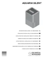
E.
Description of Operation:
The condensate flows through
the feed line
(1)
into the condensate drain and accumulates
in the housing
(2)
. A capacitive sensor
(3)
continuously reg-
isters the liquid level. As soon as the container is filled, a
fixed waiting period begins during which more condensate
accumulates. After the waiting time has expired the pilot valve
(4) is then activated and the diaphragm
(5)
opens the outlet
line
(6)
for discharging the condensate.
When the condensate drain has been emptied, the outlet
line is closed again quickly and tightly without wasting com-
pressed air.
2.0 OPERATION
Basic theory of operation: This energy saving dryer has a
completely new compressor technology at the heart of its
operation. This is the Digital Scroll. This compressor has a
unique mechanism that allows it to be completely “unloaded”.
This is accomplished internally, using a piston to “pull”
the upper scroll apart from the lower scroll. This stops the
compression of the refrigerant. At the same time: the electric
motor unloads and continues to turn, providing lubrication to the
mechanism. This greatly reduces power consumption from the
loaded state. At 100% load the compressor runs fully loaded,
with no noticeable difference between this compressor at full load
and the standard scroll compressor. The solenoid controlling the
loading and unloading cycles open and closed in response to the
temperature of the refrigerant and thereby the load on the system.
NOTE: The compressor sound changes noticeably between
the loaded and unloaded state, this occurs every ten to twenty
seconds.