


15-600 Page 8
NOTE:
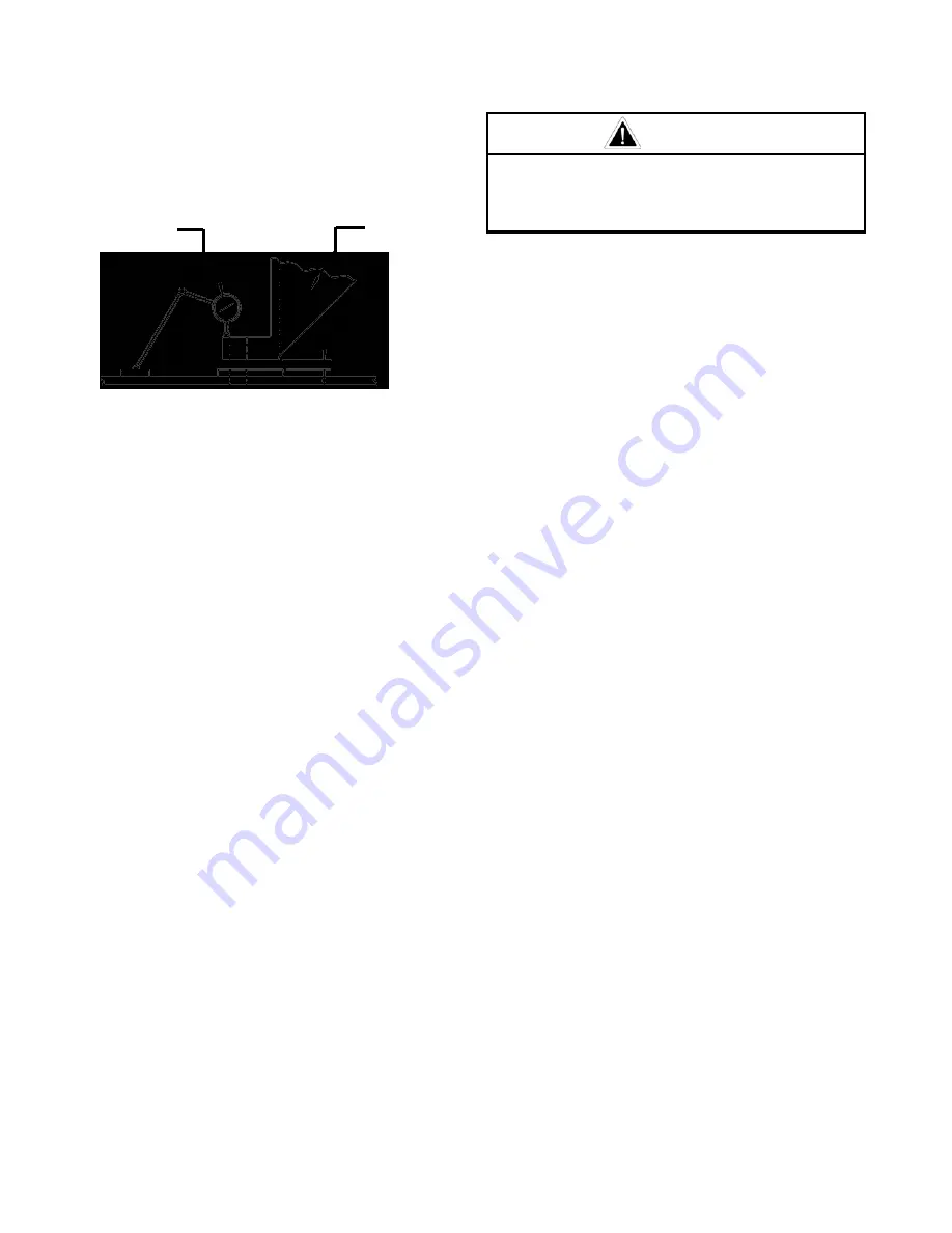
This is only when the skid is secured
to a STATIONARY foundation.
DIAL
INDICATOR
FRAME SUPPORT
FOOT
SHIM
A75738
FIGURE 1 – FINAL SHIMMING
SUCTION LINE
- Suction pipe or hose to centrifugal
charging pump should be a minimum of 12 inches
(304.8 mm) diameter and as short as possible. Always
use eccentric reducers when reducing suction pipe
size. Suction line should slope up toward the charging
pump at uniform grade to prevent air pockets being
formed. Suction line must be absolutely tight as any air
leaking into the line will reduce the capacity of the
pump and cause a hydraulic hammer or knock. If it is
necessary to have bends in the suction line they
should have long radius sweeps and be kept to a
minimum in quantity. 10 PSI - 40 PSI suction required.
Suction line should be supported near centrifugal
charging pump to keep strain from breaking the casing
at suction flange.
At least one section of hose in the suction line is
desirable to isolate pulsations or vibration. Total
suction line should be as short as installation
conditions permit.
THIS IS IMPORTANT
.
A suction strainer is recommended for the suction line
of every pump. It must be checked frequently and
cleaned whenever necessary. A commercial strainer
may be installed in suction line ahead of the pump.
It is recommended that a 50 PSI (3.515 kg/cm
2
) gauge
with a needle valve for protection be installed in the
suction line at the discharge of the centrifugal charging
pump. This gauge will indicate if pump is charging or if
suction valves are not working properly.
RELIEF VALVES
- The pump should be protected
from excess discharge pressure by a 3 inch (76.2 mm)
relief valve. This valve should be installed in a vertical
position in a tee mounted directly onto either end of
discharge manifold or discharge cross.
DANGER
Never install a shutoff valve in the line
between the pressure relief valve and
the pump discharge manifold.
If more than one pump is used, a pressure release
valve should be furnished for each pump. A hand-
operated pressure release valve should be installed in
discharge line following the relief valve, with discharge
line leading to mud tank. This valve is used to bleed air
from discharge line in starting. It is also used to relieve
pressure in starting more than one pump in parallel.
SURGE CHAMBER
- A surge chamber is essential.
One MUST be used for protection to surface
equipment and to reduce pulsations when pumping
gaseous mud. A nitrogen-charged pressure-bag type
surge chamber is recommended. The surge chamber
must be kept properly charged, as instructed by the
manufacturer.
STARTING A NEW PUMP
- It is recommended that
the drive be arranged to turn the pump in the direction
indicated by arrow shown on the sectional view in this
book, on outline prints, and indicated on pump frame.
This book provides for crosshead load to be carried on
the lower side. This means better lubrication and quiet
operation. Lube oil pumps are not automatice
reversing.
If the PZ series or the PXL pumps are to be run in
reverse direction, refer to “Lube Oil Pump”.
Pumps are shipped from the factory without oil in the
crankcase. The hood should be removed and the
power end examined and cleaned if necessary. The
pump may have been in storage or in the yard for
some time, and as a consequence, dirt may have
entered the crankcase. Drain all water accumulated in
the bottom of the crankcase. Fill crankcase with oil of
proper grade to the proper level. Quantity shown on
lubrication data plate indicates the approximate oil
requirements. All nuts and cap screws should be
checked for tightness.
It is recommended that the fluid end of the pump be
primed to prevent excessive wear on the fluid pistons
and liners when starting.
PRIMING IS IMPORTANT!
IT LUBRICATES THE PISTONS IN THE LINERS
.
Pump should be started slowly but not run below half
of rated speed. Recheck oil level as it may be
necessary to add a small quantity of oil to crankcase
and the moving parts. The pump may then be
gradually brought up to full speed and full working
pressure. Check all joints in the suction line to be sure
there are no air leaks.


