HF-7-600 Page 25
37. Using feeler gauges measure the clearance between the rotor tips and the air cylinder. This measurement
should be taken for the drive and the idler rotor. The first measurement (for both rotors) should be taken on
the inlet side of the air cylinder (by going through the inlet port). The second measurement (for both rotors)
should be taken on the discharge side of the air cylinder (by going through the discharge port). The clearance
should be measured along the entire length of the lobe and for all 3 lobes on both rotors. Record these
clearances and verify that they are within the range specified on the clearance drawing.
38. Obtain 2 gear locking assemblies (56). Each locking assembly comes with 9 capscrews. Remove 3 of these
screws. The 6 remaining screws should be in a equally spaced pattern. Note these are metric (M6) screws.
39. Clean the inside and outside diameters of both locking assemblies. Clean the inside diameter of 2 gears (9).
Clean the outside diameter of the idler and drive rotor shafts. Lightly oil the surfaces that have been cleaned.
Note: DO NOT USE MOLYBDENUM DISULFIDE, MOLYKOTE, OR ANY OTHER SIMILAR LUBRICANTS.
40. Install a spacer (55) onto the gear end of both rotor shafts. Note this is a stepped spacer. The narrow end
should be in contact with the bearing inner race.
41. Slide a locking assembly into a gear. The slits in the inner ring and in the outer ring must not be in line with
each other. Install the gear and locking ring assembly onto the idler rotor shaft.
42. Push the locking assembly firmly up against the shaft spacer and hand tighten the 6 capscrews.
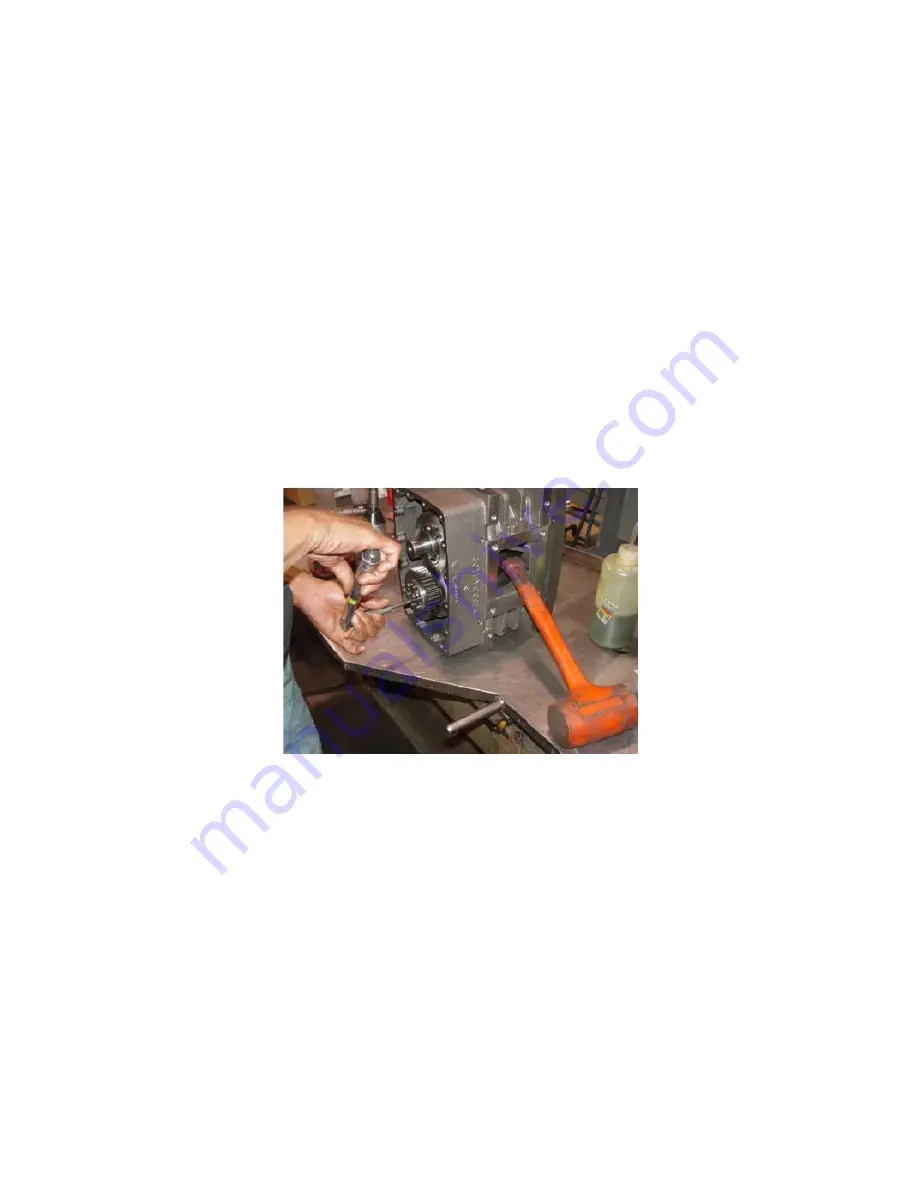
FIGURE 7-6 – TIGHTEN GEAR LOCKING SCREWS
43. Use a torque wrench to tighten the screws to 50 in.lbs in a diametrically opposite sequence. Ensure that
none of the screws will turn when 50 in.lbs is applied to them a second time. See
FIGURE 7-6
.
44. Tighten the screws further to 100 in.lbs in a diametrically opposite sequence. Ensure that none of the screws
will turn when 100 in.lbs is applied to them a second time.
45. Tighten the screws to a final torque of 150 in.lbs in a diametrically opposite sequence. Ensure that none of
the screws will turn when 150 in.lbs is applied to them a second time.
46. Slide a locking assembly into a gear. The slits in the inner ring and in the outer ring must not be in line with
each other. Install the gear and locking ring assembly onto the drive rotor shaft. Note the circular mark on
each gear indicates the position of the largest runout. These marks must be 180 degrees apart when the
gears are installed.
47. Push the locking assembly firmly up against the shaft spacer and hand tighten the 6 capscrews but leave
them loose enough that the gear can be rotated on the shaft.


